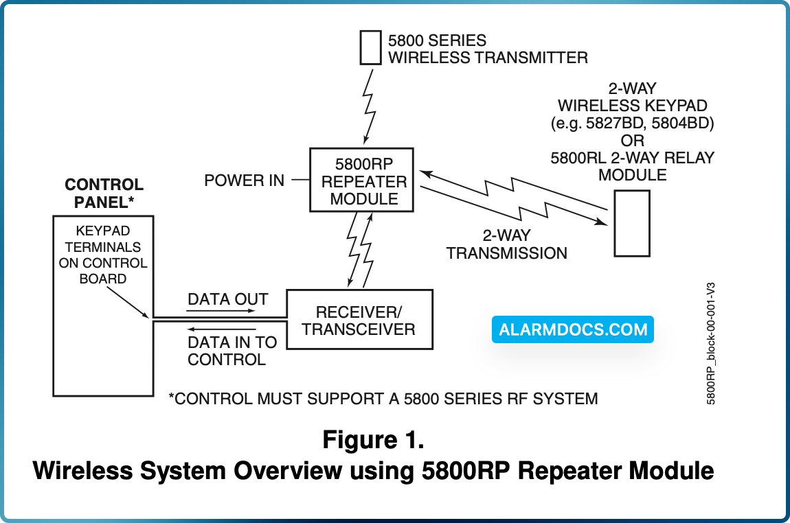
The 5800RP RF Repeater Module consists of an RF receiver and a transmitter and is intended to extend the range of 5800 series RF devices by 200 feet (nominal).
The 5800RP receives alarm, status, and control messages from 5800 series devices, and forwards these messages to control panel connected receivers such as the 5881EN, 5883, 6128RF, 6150RF, and LYNX controls. The control then responds accordingly (arm/disarm the system, initiate an alarm, etc.).
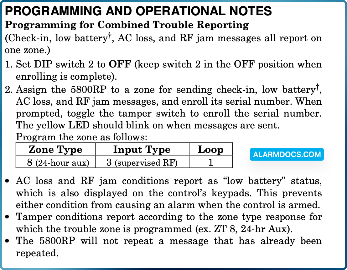
The 5800RP also transmits its own status including tamper, AC loss and RF jam detect via a built-in serial number assigned to a control panel zone(s). Status is sent whenever a change occurs or as part of a supervisory check-in message sent approximately once an hour.
The 5800RP contains a rechargeable battery that provides up to 6 hours of standby operation after primary power is lost. The 5800RP features a Spatial Diversity system that virtually eliminates the possibility of “Nulls” and “Dead Spots” within the coverage area.
INSTALLING THE 5800RP MODULE
Mount the 5800RP remotely in its own housing following the steps below, and avoid mounting the module with its antennas touching a metal surface.
Removing the Cover: Remove the 5800RP’s cover by inserting and twisting a screwdriver blade in the slot at the center of the cover’s lower edge. Note that removing the cover also places the 5800RP in the Go/No Go Test mode. This decreases its range during installation to insure an adequate margin during normal operation.
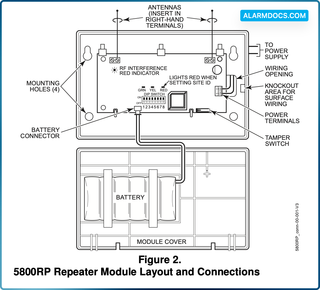
Mounting the Module
1. For concealed wiring, route power wires through the rectangular opening at the rear of the base before mounting. For surface wiring entry, a thin breakaway area is provided along the base’s right edge.
2. Mount the module in the selected location. For greatest security, use all four mounting holes (two keyslot holes and two round holes) in the plastic base.
3. Install each antenna in the respective right-hand terminal of the two terminal blocks at the upper edge of the 5800RP’s circuit board, and tighten the screws to secure them.
4. Affix the Summary of Connections label to the inside of the module’s cover. Make sure the arrows and large ‘plus sign’ on the label line up with the corresponding posts in the cover.
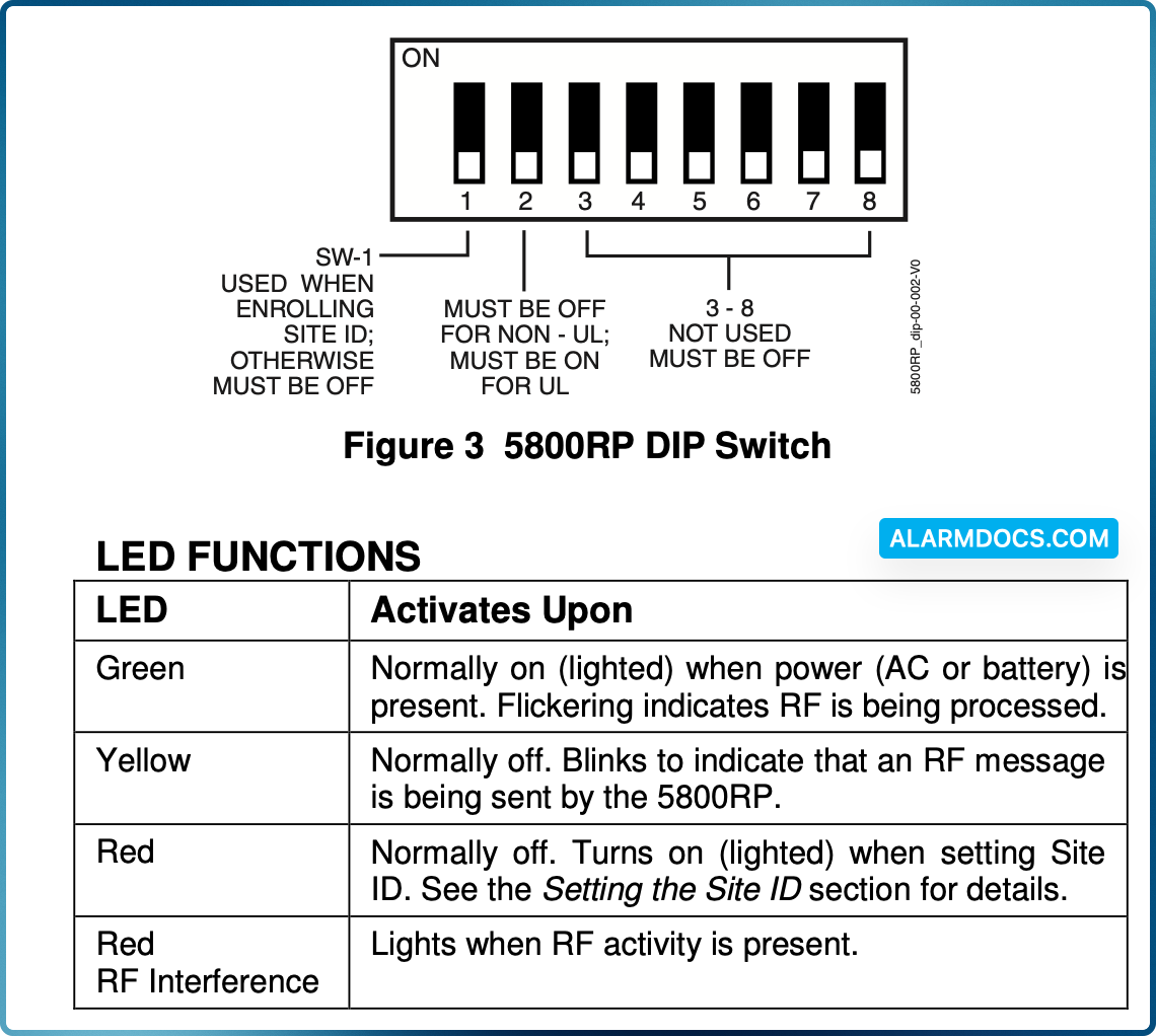
5. If applicable, set the Site ID
Connecting the Power Source
The 5800RP is powered from an AC external power source connected to terminals 1 and 2 (see figure 2). Power source ratings are as follows:

6. Connect the transformer to the 5800RP’s terminals. Refer to Figure 2. These terminals are not polarized. The leads from the AC transformer may be connected to either terminal. Do not connect to a receptacle controlled by a switch.
Connecting the Battery
7. Begin battery installation by attaching an adhesive backed hook and loop fastener strip (supplied) to the Summary of Connections label in the cover. Place the strip within the large box drawing labeled ‘PLACE BATTERY HERE’. Refer to Figure 2.
8. Attach another adhesive backed hook and loop fastener strip to the battery. Attach the battery to the cover by firmly pressing the two hook and loop fastener strips together. Make sure the battery is positioned as shown in Figure 2.
9. Plug the battery cable into the battery connector on the 5800RP PCB.
10. Replace the cover on the 5800RP, being careful not to pinch the battery wires between the cover and case or any PCB components.
SETTING THE SITE ID
Some wireless devices (e.g., 5827, 5804BD) use a programmed house ID to help avoid communication conflicts with nearby installations. The 5800RP automatically passes all house ID information to the appropriate receiver.
Certain wireless devices, such as the 5883, use a “Site ID” instead of a House ID. The Site ID is a factory-assigned, unique serial number built into each 5883 transceiver and must be entered into each device that uses it. The Site ID provides many more combinations than a House ID, and therefore is less likely to have conflicts with nearby installations.
When using the 5800RP with wireless devices that use a Site ID, follow the steps below to enter the Site ID in the 5800RP. This procedure assumes that all such devices have been successfully set-up and tested with the 5883, although they may not yet be mounted in their final locations.
1. Put the control (and the 5883) in the Go/No Go Test mode.
2. Remove the 5800RP’s cover by inserting and twisting a screwdriver blade in the slot at the center of the cover’s lower edge. Note that removing the cover also places the 5800RP in the Go/No Go Test mode. This decreases its range during installation to insure an adequate margin during normal operation.
3. Temporarily disconnect the power source and battery from the 5800RP. Refer to Figure 2.
4. Place DIP switch 1 in the ON position.
5. Reconnect the power source to the 5800RP. Observe that the red LED on the 5800RP turns on and remains on. This indicates that the 5800RP is ready to set the Site ID.
6. Push, release, then hold down the tamper switch on the 5800RP until the red LED turns off.
7. The red LED turning off indicates that the Site ID has been saved in the 5800RP. If the LED does not turn off, repeat the previous step until it does.
8. Place DIP switch 1 in the OFF position.
9. Replace the cover on the 5800RP.
10. Take the control out of the Go/No Go Test mode.
11. If needed locate the other wireless devices in their final locations.
12. Test all wireless devices.