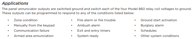
Dry relay contacts on the 860 Module are programmable and controlled from panel annunciator outputs. The module includes one Form C (SPDT) relay rated for 1 Amp at 30 VDC. The 860 Module also provides three additional sockets for Model 305 Plug-In Output Relays (12 VDC).
Relays can be used for electrical isolation between systems or for switching 5, 12, or 24 Volts to control various functions within a building or around its perimeter.
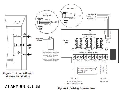
MOUNT THE MODULE
The module can be mounted in a DMP enclosure using the standard 3‑hole mounting pattern. Refer to Figure 2 as needed during installation.
- Hold the plastic standoffs against the inside of the enclosure side wall.
- Insert the included Phillips head screws from the outside of the enclosure into the standoffs. Tighten the screws.
- Carefully snap the module onto the standoffs.
WIRE THE MODULE
Refer to Figure 3 as needed during wiring. For power connections, use 22 AWG or larger wire.
- Connect the included 4‑wire harness from the module RELAY COILS header to the panel OUTPUTS header.
- Connect a wire from the 860 Power Terminal (+12) to panel Terminal 7 (RED) or a DMP Model PS12-5 (DC+).
- To install additional Model 305 relays, ensure the half-circle notches on the relay and relay socket are facing the same direction, then gently press the relay, with the pins facing down, into the socket.
- Connect relay terminals NO, C, and NC to devices as needed for each installed relay. Refer to Applications for more information.
ADDITIONAL INFORMATION
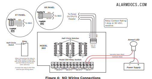
Normally Open (NO) Wiring
Refer to Figure 4 as needed during wiring. For power connections, use 22 AWG or larger wire. Complete the following steps:
- Connect the included 4‑wire harness from the module RELAY COILS header to the panel OUTPUTS header.
- To install additional Model 305 relays, ensure the half-circle notches on the relay and relay socket are facing the same direction, then gently press the relay, with the pins facing down, into the socket.
- Connect relay terminal NO to the device (DC+), such as an armed LED.
- Connect relay terminal C to the power supply (DC+), such as the PS12-5.
- Connect the device (DC-) to the power supply’s (DC-).
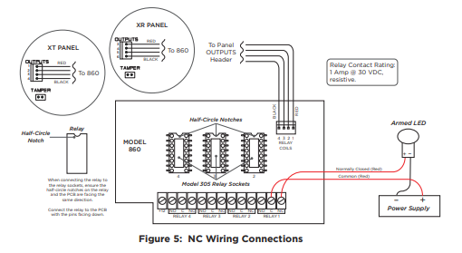
Normally Closed (NC) Wiring
Refer to Figure 4 as needed during wiring. For power connections, use 22 AWG or larger wire. Complete the following steps:
- Connect the included 4‑wire harness from the module RELAY COILS header to the panel OUTPUTS header.
- To install additional Model 305 relays, ensure the half-circle notches on the relay and relay socket are facing the same direction, then gently press the relay, with the pins facing down, into the socket.
- Connect relay terminal NC to the device (DC+), such as an armed LED.
- Connect relay terminal C to the power supply (DC+), such as the PS12-5.
- Connect the device (DC-) to the power supply (DC-).
Wiring Specifications
DMP recommends using 18 or 22 AWG for all LX‑Bus and Keypad Bus connections. The maximum wire distance between any module and the DMP Keypad Bus or LX‑Bus circuit is 1,000 feet. To increase the wiring distance, install an auxiliary power supply, such as the DMP Model PS12-5. Maximum voltage drop between a panel or auxiliary power supply and any device is 2.0 VDC. If the voltage at any device is less than the required level, add an auxiliary power supply at the end of the circuit.
To maintain auxiliary power integrity when using 22‑gauge wire on Keypad Bus circuits, do not exceed 500 feet. When using 18‑gauge wire, do not exceed 1,000 feet. Maximum distance for any bus circuit is 2,500 feet regardless of wire gauge. Each 2,500 foot bus circuit supports a maximum of 40 LX‑Bus devices.