PGP922 detects shattering glass. Like all glass-break sensors, the detector might not consistently detect cracks in glass, or bullets that break through or break out the glass. Glass-break sensors should always be backed up by interior protection.
Areas to avoid:
- Glass airlocks and glass vestibule areas
- Noisy kitchens
- Residential car garages
- Small utility rooms
- Stairwells
- Small bathrooms
- Humid rooms
Enrolling the device
Qolsys 4
- On the main screen of your IQ Panel 4, swipe down from the top to open the Settings Tray.
- Tap on Settings.
- Tap on Advanced Settings (usually located at the bottom right).
- Enter your Installer Code or Dealer Code. The factory default Installer Code is 1111, and the default Dealer Code is 2222.
- Tap on Installation, then select Devices, and finally Security Sensors.
- Tap Auto Learn Sensor on the screen. The panel will now be “listening” for a PowerG signal.
- Open the sensor’s cover to expose the battery and the internal Enrollment/Pairing Button.
- Press and hold the enrollment button until the LED light on the sensor flashes (usually orange or yellow), then release it.
- Alternatively, for some PowerG sensors, simply inserting the battery or tripping the “tamper” switch by closing the cover will send the enrollment signal.
- The panel should beep and display a prompt asking if you want to add a sensor with the detected ID (e.g., a 7-digit number starting with 10x-xxxx). Tap OK.
PowerSeries Neo
- From the keypad, press * then 8 then the Installer Code (default is 5555).
- Enter 804 to go to the wireless programming menu.
- Press
*to select “Enroll Device”. - Activate the sensor by pressing and holding its enrollment button (usually under the cover) or pulling the battery tab until the LED lights, then release.
- The keypad will display the sensor’s serial number (ID). Press * to confirm it’s correct.
- Enter the 3-digit zone number you want to assign (e.g., 001,002).
- Enter the 3-digit code for the sensor’s function (e.g., “Door/Window”, “Motion”) from the manual.
- Ensure ‘Y’ (Yes) is shown for Partition 1 (or toggle with * if needed).
- Press
#to move to zone label programming (if using an LCD keypad) and enter a descriptive label (e.g., “Front Door”). - Press
#to move to the next zone or press#repeatedly to exit programming and return to the main screen. - After programming, test the sensor to confirm it’s working correctly with the system.
Mounting the device using tape
1. Peel the release liners off the two strips of double-sided adhesive tape and attach the tape to the back of the device. See the following figure.
Figure 2: Double-sided adhesive tape placement on the device
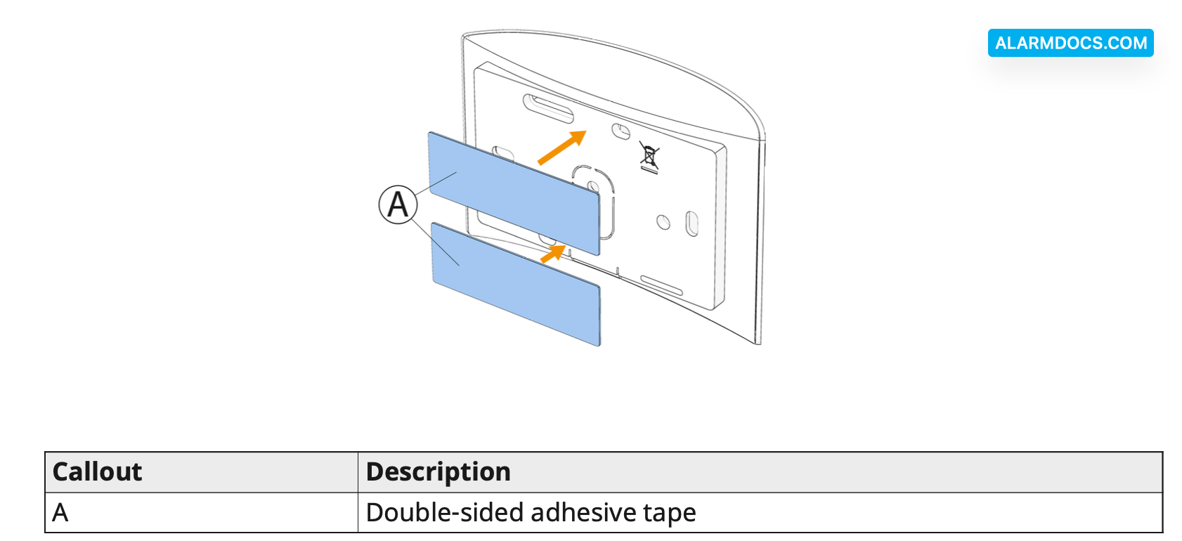
2. Place the device on the desired surface.
Figure 3: Typical range coverage
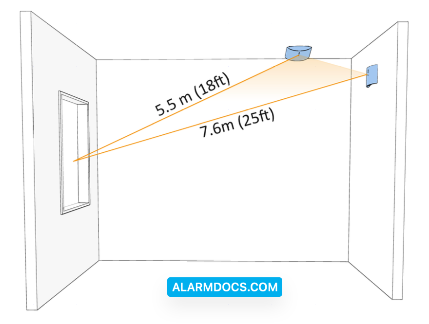
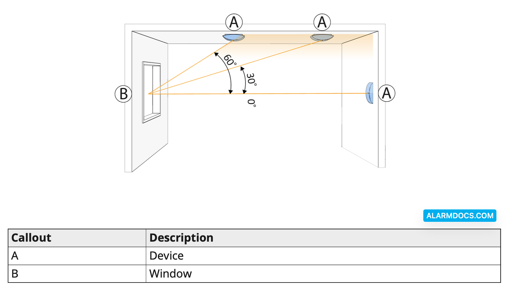
When mounted on opposite walls, on adjoining walls or on the ceiling, the range is 7.6 m (25 ft) for plate, tempered, laminated, wired, coated, and sealed insulating glass. The coverage range also depends on the angle between the detector and the glass. For a higher angle, the maximum range is reduced. See the following table and figure for details.

Figure 4: Angle between device and window top view
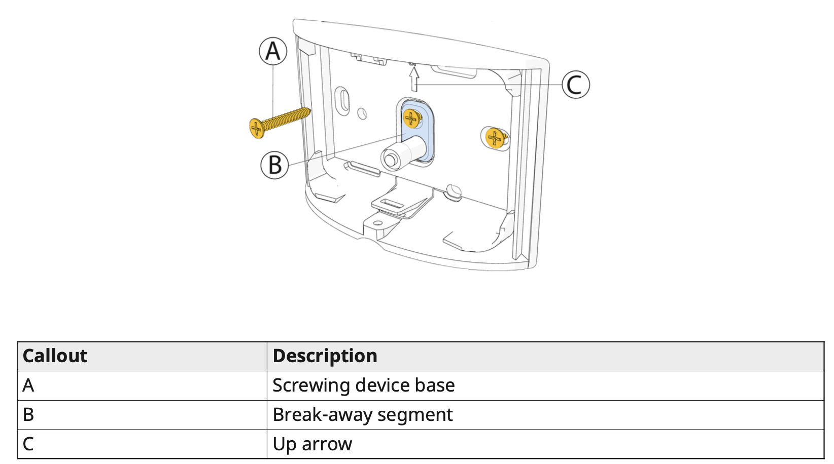
Mounting the device using screws
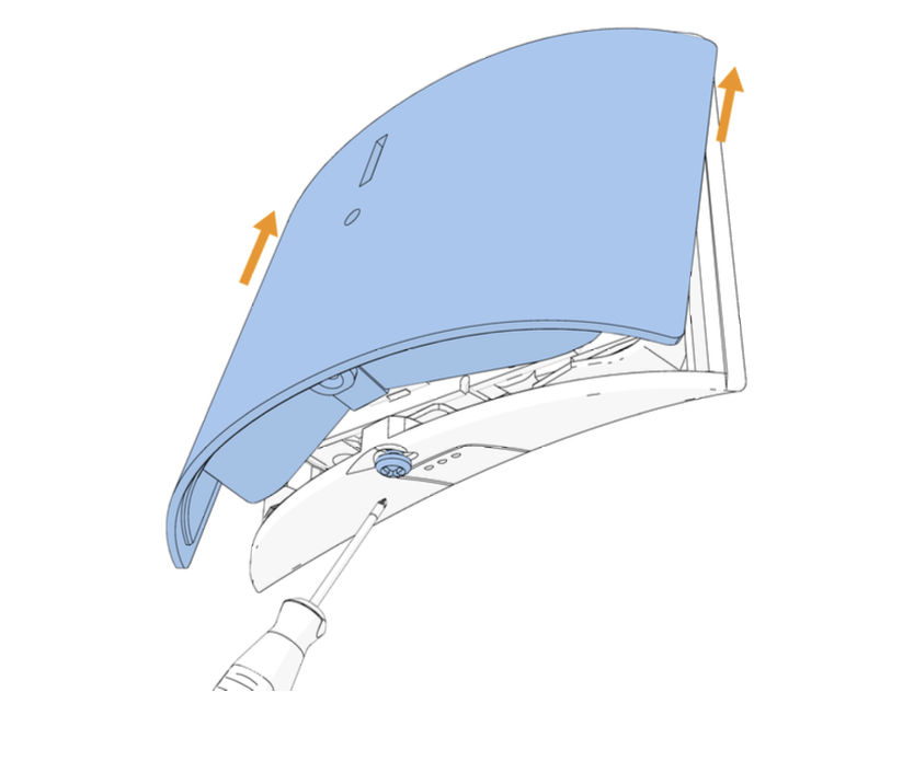
To open the device cover, press in the snap and separate the cover from the base.
Screw the device base to the wall. Ensure the device is correctly orientated using the arrow as a guide.
Figure 5: Device screw installation
Clip the cover on the device base and tighten the cover screw. See the following figure.
Figure 6: Closing the device cover
Replacing the battery
1. Remove the device cover.
2. Remove the battery.
3. Insert the battery into the battery clips while observing battery polarity.
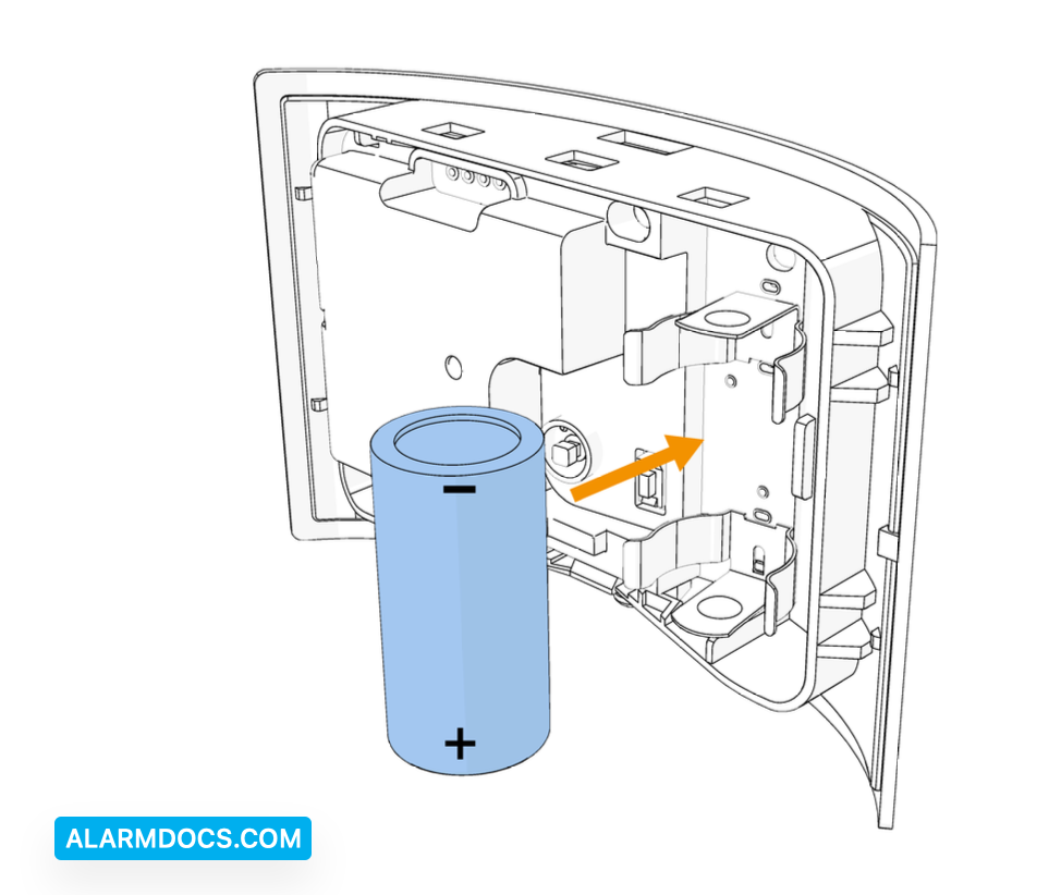
4. Press down on the battery until it fits into place.
5. Close the cover and fasten the cover screw. See Figure 6.
Local diagnostics test
After power-up or closing the cover, the device automatically enters Test Mode for 15 minutes.
- Before you start the test, remove the device cover from the base.
- Close the cover to return the tamper switch to its normal position.
- After 10 seconds the LED blinks three times.
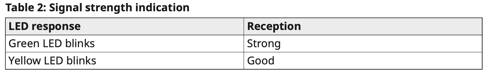
The following table indicates received signal strength indication.