The IntelliSense® IS-310 is a Request-to-Exit Passive Infrared (PIR) sensor. Mounted near an exterior door inside a building with an access control system, the sensor provides free exit to individuals within the building without causing an alarm.
The parts of the IS-310 are shown below.
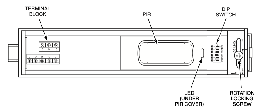
Mounting Location
The IS-310 can be mounted on the wall or ceiling.
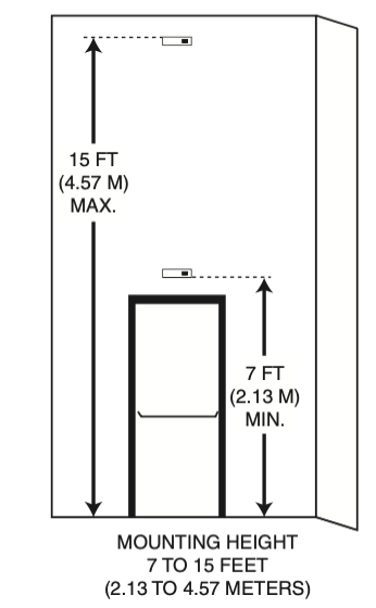
Choose a mounting location that:
- Gives the sensor a clear line-of-sight to every part of the detection area. Infrared energy cannot penetrate solid objects; if the PIR cannot detect movement, the sensor will not activate.
- Does not place the sensor directly across from one or more windows.
- Is away from moving machinery, fluorescent lights and heating and cooling sources.
The mounting locations available for a request-to-exit sensor can be fairly limited. You may find that it is impossible to avoid a source of false detection within the IS-310’s detection pattern. In that case block the sensor’s view of that portion of the pattern by adjusting the shutters as described in shutter adjustment section bellow.
Mounting Procedure
To mount the sensor, do the following:
- 1. Open the sensor housing by pressing on the latch with a screwdriver. This latch is located on the end of the sensor nearest the lens. Pull the cover up and away from the sensor’s base.
- 2. Loosen rotation locking screw two (2) turns (do not remove). Then, remove PCB assembly from the backplate of the sensor.
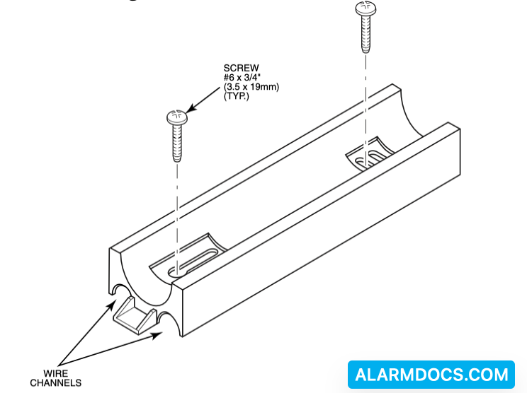
- 3. Insert the wiring into one of the wire channels on the sensor’s backplate.
- 4. Securely affix the sensor’s backplate to the wall or ceiling using 2 #6 X 3/4 inch (3.5 X 19 mm) screws provided.
- 5. Reinstall the PCB assembly and adjust for short or long range as described in section 6. Then, tighten rotation locking screw.
Input/Output Description
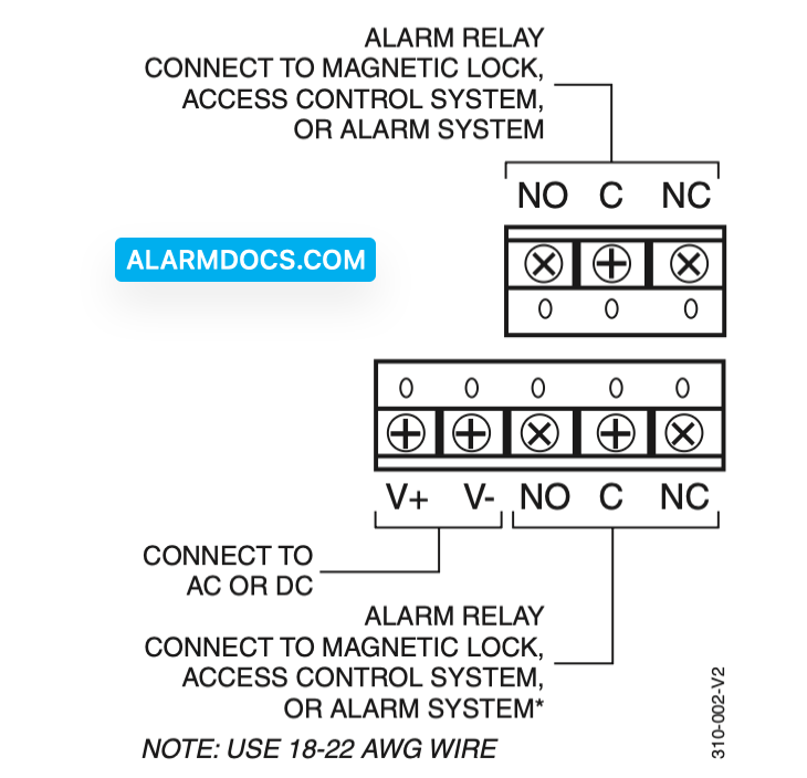
The IS-310 inputs and outputs are as follows: V+/V–: Connects to AC or DC power (12 to 28 volts).
Relays
Input/Outputs for the unit’s dual double pole/double throw relay. The relay may be used to control a magnetic lock or signal an access control system. All relay connections (common, normally closed, and normally open) for both sets of contacts are available on the terminal block.
IS-310 Wiring
Wire the sensor as shown in the illustration.
Long Range/Short Range Adjustments
The IS-310 can be set to detect individuals at either a long range (several steps from the door) or at short range (immediately in front of the door). If the building includes a lengthy approach to the exit doorway and no other foot traffic in the area, choose the long-range setting.
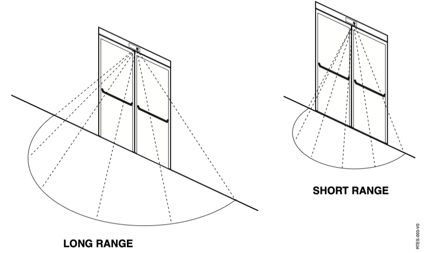
Choose between long- and short-range detection patterns
To set the range length:
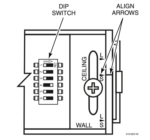
1. Loosen the rotation locking screw.
2. Turn the PCB in its rotating base until the arrow on the base is aligned with the appropriate notch on the baseplate. If the sensor is ceiling mounted, choose between the notches with the “Ceiling” label. If the sensor is wall mounted, choose between the notches with the “Wall” label. The arrow on the mounting base (or back plate) needs to be aligned with the ceiling or wall arrows. The “L” designates long range and the “S” designates short range.
3. Tighten the rotation locking screw.
Shutter Adjustment
The IS-310 contains shutters behind the PIR cover. These shutters are used to adjust the field width. This may be necessary when the unit is installed where it may be tripped by non-exiting foot traffic or other erroneous sources at either or both edges of the detection area.
- To adjust the shutters, remove the lens cover from the PIR.
- Push the forward edge of the shutter(s) toward the middle of the opening until the area(s) to be blocked are outside the line-of-sight of the PIR. When making the shutter adjustment, each shutter position has a detent and each detent masks off an entire detection zone. There are eight zones total and each shutter has the ability to mask off 7 of the 8 zones. If the shutter is located between detents, the result will be an attenuation of a zone that is intended to be masked or attenuation of a detection zone resulting in improper operation.
- Replace the lens cover.
DIP Switch Settings
The IS-310 DIP switch contains 6 switches for selecting operating options. The functions of these switches are as follows:
Switch 1 – Sensor Mode (Sensitivity) Selector: OFF is the Request-to-Exit mode. ON is the Security Sensor mode. In the security sensor mode, the sensor is more immune to false alarms, but the extra time required to perform signal qualifications may make the unit unsuitable for most RTE applications. The unit is shipped in the Request-to-Exit mode.
Switch 2 – LED Disable: This switch must be off to allow the LED to function. The unit is shipped with the LED enabled (switch OFF).
Switch 3 – Relay Timer Mode: This switch selects the relay timer re-trigger or fixed modes. With this switch OFF, the re-trigger mode is selected. In the re-trigger mode, the relay timer is restarted with the time programmed (with switches 4, 5, and 6) whenever motion is detected. The relay will only de- activate when the time programmed expires without additional motion detected during the active period. With this switch ON, the fixed mode is selected and the relay will deactivate at the expiration of the relay time programmed (with switches 4, 5, and 6) and additional motion detection during the active period has no effect. The unit is shipped with this switch OFF (re-trigger mode).
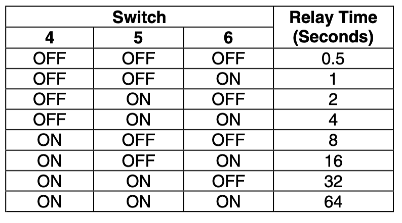
Switches 4, 5, and 6 – Relay Timer Setting: These switches control the relay timing: To set the relay timing, refer to the following table:
Walk Testing
Walk into the motion detection field. Two to four normal steps into the field should make the LED light.
Each time the LED goes on, wait for it to go off. Then wait 12 seconds before continuing the walk-test. When there is no motion in the detection field, the LED should be off.
Specifications
| Range | Long: 8.4’ x 15.8’ (Adjustable) 2.6m x 4.8m (Adjustable) Short: 2’ x 5.5’ (Adjustable) 0.5m x 1.7m (Adjustable) |
| RFI Immunity | 30 V/m, 1 MHz – 1000 MHz |
| White light immunity | 2000 Lux |
| Relay (Dual) | Form C Contact rating; 1A max. at 30 VDC max. |
| Power requirements | 12 to 28 VDC or VAC 3V peak-to-peak @ 12.5V <50 mA current consumption |
| Accessories | IS-310WHTP – Single gang trim plate, White IS-310BLTP – Single gang trim plate, Black |
| Operating temp | 32° to 122°F (0° to 50°C) |
| Part numbers | S-310WH – White Housing IS-310BL – Black Housing |
| Size | 7” x 2” x 2” 17.8cm x 5.1cm x 5.1cm |
| Relative humidity | <95% non-condensing |