The 1142INT is a wireless two‑button hold-up transmitter designed for installation under the counter. The 1142INT features 128‑bit AES encryption.
The 1142INT unit provides two buttons that, when pressed at the same time, send a panic message to the control panel. The buttons also provide an LED that can be programmed to provide visual indication that a panic alarm has been transmitted.
Compatibility
- 1100XINT Wireless Receivers Version 700 and Higher
- 1100DINT Wireless Receivers Version 700 and Higher
- XT30INT/XT50INT Series Panels Version 693 and Higher
- XTLplusINT/XTLtouchINT Series Panels Version 693 and Higher
- XR150INT/XR550INT Series Panels Version 693 and Higher
PROGRAM THE PANEL
When programming the 1142INT in the panel, refer to the panel programming guide as needed. For your convenience, an additional pre‑printed serial number label is included.
1. In ZONE INFORMATION, enter the wireless ZONE NO:.
2. Enter the zone name.
3. Select PN (panic) as the ZONE TYPE.
4. At the NEXT ZN? prompt, select NO.
5. Select YES when WIRELESS? displays.
6. Enter the eight-digit SERIAL# and press CMD.
7. Enter in the SUPRVSN TIME (supervision time) and press CMD.
8. At LED OPER (operation), select YES to activate or NO to not activate the LED when a panic signal is transmitted or acknowledged by the receiver. The LED pulses for five minutes after the acknowledgement is received from the panel.
9. At the NEXT ZN? prompt, select YES if you are finished programming the zone. Select NO if you would like to access additional programming options.
10. In SYSTEM OPTIONS, at the 1100 ENCRYPTION prompt, select ALL to only add encrypted wireless devices to the system. Select BOTH to allow both encrypted and non- encrypted wireless devices to be programmed.
11. The default passphrase appears at ENTER PASSPHRASE. Press CMD to keep the default. Press any select key or area to change the passphrase and enter an 8‑character hexadecimal string (0‑9, A‑F).
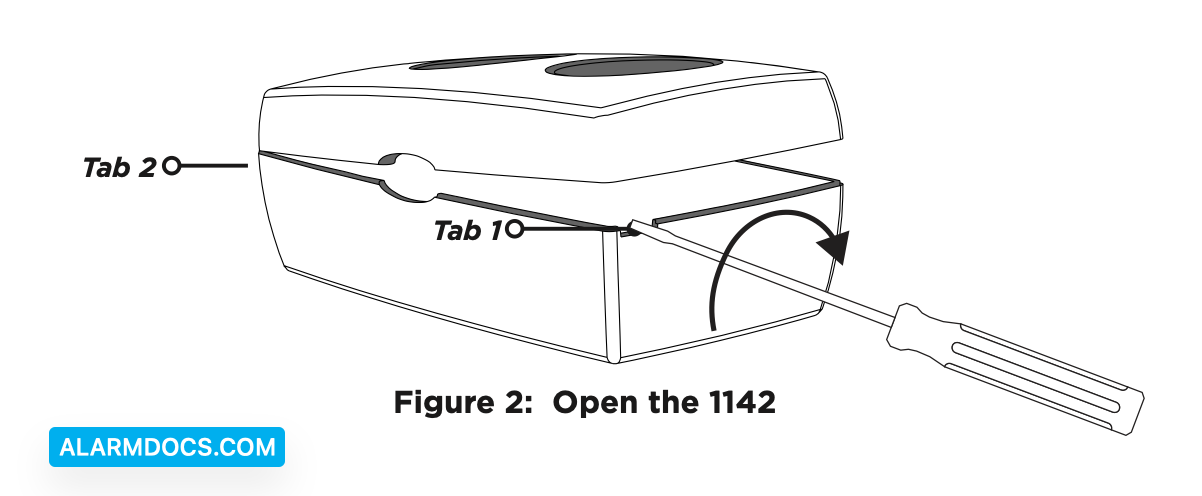
OPEN THE 1142INT
Because of the strength and the snap-on design of the plastic, the 1142INT can only be opened by using a 4.8 mm slotted tip screwdriver.
1. Insert the screwdriver in Tab 1 and twist it clockwise.
2. Insert the screwdriver in Tab 2 and twist it counterclockwise until the housing completely opens.
INSTALL THE BATTERY
Use a 3.0 V lithium battery or a DMP Model CR123A battery. When setting up a wireless system, program zones and connect the receiver (if needed) before installing the battery.
With the transmitter already open, observe polarity and place the battery in the holder and press it into place.
SELECT A LOCATION
The transmitter provides a survey capability to allow one person to confirm communication with the wireless receiver or panel while the cover is removed. This allows you to determine the best location for the transmitter.
Check the Location Using a Survey LED
1. Hold the 1142INT in the exact desired location.
2. Press the tamper switch to send data to the panel and determine if communication is confirmed or faulty.
3. Relocate the transmitter or receiver until the LED confirms clear communication. Proper communication between the transmitter and panel is verified when for each press or release of the tamper switch, the LED blinks immediately on and immediately off.
MOUNT THE 1142INT
1. MOUNT THE 1142INT Set aside the top housing containing the PCB and the battery.
2. Place the base housing in the desired location with the LED cut–out facing you.
3. Use the two supplied Phillips screws to mount the base.
4. Install a screw in the tamper location if required.
5. Align the top housing and LED cut–out with the base housing and LED cut–out and snap into place. Ensure the tamper in the top housing is aligned with the tamper location on the base housing.
WALK TEST THE 1142INT
After the transmitter has been installed, perform a Walk Test to confirm the transmitter is communicating with the panel.
1. At the keypad, enter 8144 (WALK) and select WLS.
2. If the transmitter fails to check in at the keypad, relocate the wireless device or receiver. Repeat the survey LED test followed by the Walk Test until the transmitter checks in at the keypad.
Sensor Reset to Clear LOBAT
When the battery needs to be replaced, a LOBAT message will display on the keypad. Once the battery is replaced, a sensor reset is required at the system keypad to clear the LOBAT message.
1. On a Thinline keypad, press and hold “2” for two seconds. On a touchscreen keypad, press RESET.
2. Enter your user code if required. The keypad displays SENSORS OFF followed by SENSORS ON.