The DMP Model 7060, 7063, 7070, and 7073 Thinline™ LCD Keypads offer the same flexible features and functionality as current DMP keypads in a stylish, sleek new design. Each keypad provides four 2-button Panic keys, AC power LED, Armed LED, 32-character display, backlit logo and keyboard with easy-to-read lettering and an internal speaker. In addition, the Models 7070 and 7073 keypads also provide four fully programmable Class B, Style A protection zones you can program for a variety of burglary and access control applications.
The Model 7063 and 7073 keypads provide a built-in proximity card reader designed to read HID 1300 Series proximity credentials. The Model 7073 keypad also provides a door strike relay and allows Wiegand input from HID, DMP, or other external card readers.
Installing the Keypad
The keypad housing is designed to easily install on any 4” square box, 3-gang switch box, DMP 695 and 696 backbox, or a flat surface.
Removing the Base
The keypad housing is made up of two parts: the front, which contains the circuit board, keyboard components, and the base. To remove the base, insert a flat screwdriver into one of the openings on the bottom and twist the screwdriver while pulling the halves apart. Repeat with the other opening.
Harness Wiring
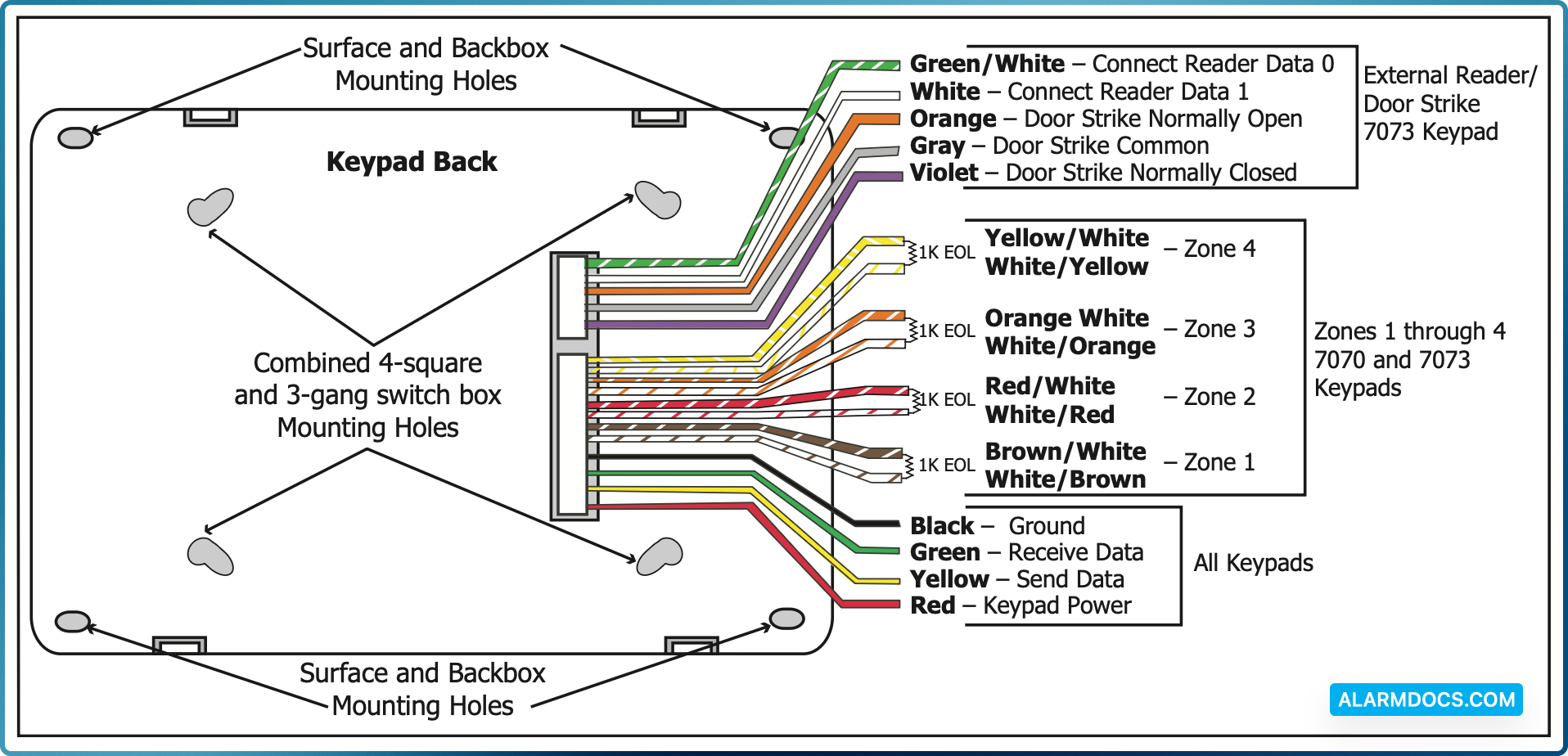
Figure 1 shows wiring harness assignments. Observe wire colors when connecting the red, yellow, green, and black wires to the keypad bus. When wiring directly to the panel terminals, connect red to panel terminal 7, yellow to terminal 8, green to 9, and black to panel terminal 10. Use 1k Ohm EOL resistors, DMP Model 311, on keypad zones 1 through 4.
The 7060 and 7063 keypads are supplied with a 4-wire harness for panel keypad bus connection.
The 7070 and 7073 keypads are supplied with a 12-wire data bus/zone harness. Four wires connect to the keypad bus. The remaining eight wires are for the four zone inputs: two wires for each zone.
The 7073 keypad is also supplied with one 5-wire output/reader harness.
Figure 1: Keypad Back Showing Wiring Harness Assignments
Additional Power Supply
If the current draw for all keypads exceeds the panel output, you can provide additional current by adding a Model 505-12 auxiliary power supply. Connect all keypad black ground wires to the power supply negative terminal. Run a jumper wire from the power supply negative terminal to the panel common ground terminal. Connect all keypad power (+12 VDC) wires to the power supply positive terminal. Do NOT connect the power supply positive terminal to any panel terminal.
Keypad Bus Monitor
For UL Listed fire protective systems, the 893/893A Module must be installed in the XR500 Series or XR200 control panel to monitor the keypad bus and sound an audible trouble whenever the keypad bus fails to operate.
Card Readers
When a proximity credential is presented to an internal or external reader, a beep tone is heard and the Power and Armed LEDs blink. This provides both an audible and visual acknowledgement of the credential read.
Internal Access Control Reader
The 7063 and 7073 keypads provide a built-in proximity card reader designed to read HID 1300 Series proximity credentials.
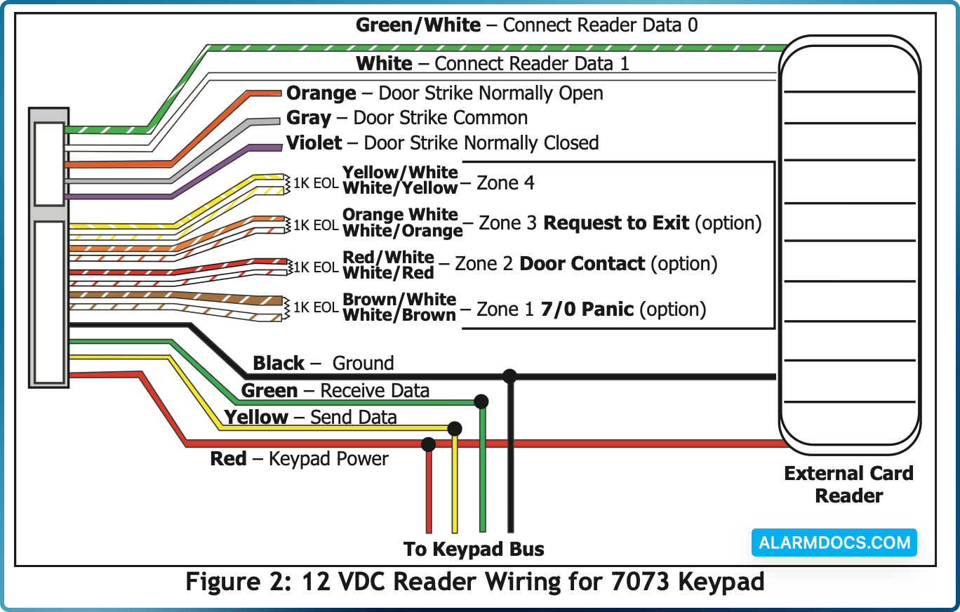
External Access Control Reader
To accept Wiegand data input from HID, DMP, or other external card readers, connect a 12 VDC external reader to the 7073 keypad. Connect the Red and Black power wires from the reader to the power wires from the panel. These connect in parallel with the keypad power wires. Connect the Reader (Data 1) wire to the White wire on the 5-wire keypad harness. Connect the Reader (Data 0) wire to the Green/White wire on the 5-wire keypad harness.
7073 Door Strike Relay Specifications
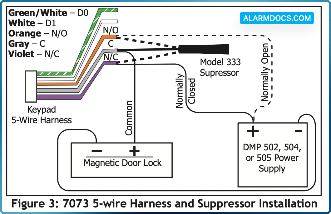
The 7073 keypad provides one internal Form C single pole, double throw (SPDT) relay for controlling door strikes or magnetic locks. Three wires on the 5-wire harness, Violet (N/C), Gray (Com), and Orange (N/O), allow you to connect devices to the relay. The Form C relay draws up to 15mA of current and its contacts are rated for 1 Amp at 30 VDC maximum.
Wiring the 333 Suppressor
One Model 333 Suppressor is included with the 7073 keypad. Refer to Figure 3 and install the suppressor across the 5-wire output/reader harness Common (C) and Normally Open (N/O) or Normally Closed (N/C).
If the device being controlled by the relay is connected to the N/O and C wires, install the suppressor on the N/O and C wires. If the device is connected to the N/C and C wires, install the 333 Suppressor on N/C and C wires.
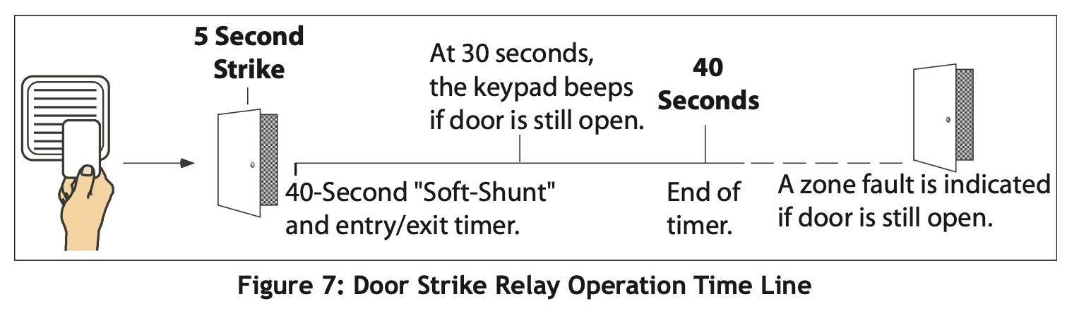
7073 Door Strike Relay Operation
As soon as the user code sent from the reader is verified by the panel, the keypad door strike relay activates for 5 seconds. During this time, the access door connected to Zone 2 must be opened to start the programmed entry/exit timer and zone Soft-Shunt.
7073 Zone 2 Door Contact with Soft-Shunt™
If the door being released by the keypad is protected, you can provide a programmed shunt time by connecting its contact to Zone 2 (White/Red pair) on the keypad and enabling the Soft-Shunt feature. See ZONE 2 SHUNT later in this document. Door contacts may be N/C or N/O.
7073 Zone 3 Request to Exit
You can also connect a normally open PIR (or other motion sensing device) or a mechanical switch to Zone 3 (White/ Orange pair) on the keypad to provide a request to exit capability to the system. See ZONE 3 EXIT later in this document. When Zone 3 shorts, the keypad relay activates for 5 seconds. During this time, the user can open the protected door to start the programmed Soft-Shunt entry/exit timer. If the door is not opened within 5 seconds, the relay restores the door to its locked state.
Installer Options Menu
The 7000 Series keypads provide Keypad Option and Keypad Diagnostic menus to allow installers and service technicians to configure and test keypad operation.
Accessing Installer Options
You can only access the Installer Options Menu through the User Options function. Hold down the <— and CMD keys for two seconds to display SET BRIGHTNESS. Enter the code 3577 (INST) and press CMD. The display changes to KPD OPT (keypad options) KPD DIAG (keypad diagnostics) and STOP.
The Keypad Options menu allows you to set the keypad address, select Supervised or Unsupervised mode, change the default keypad message, selectively enable the 2-button Panic keys, Soft-Shunt, Request-to-Exit, and set entry card options.
Zone 2 Soft-Shunt Time (7073 only)
Enter the number of Soft-Shunt seconds to elapse before the Soft-Shunt timer expires. Range is from 20 to 250 seconds. Press any top row select key to enter the number of seconds. Once the door strike relay is activated, the user has 5 seconds to open the door connected to zone 2. The zone is then shunted for the programmed time or until the contact restores to normal. Ten seconds after the Soft-Shunt entry/exit time begins, the keypad beeps if the door is still open. If the door remains open when the timer expires a zone open/short is sent to the panel for Zone 2. The default is 40 seconds.
Relock on Zone 2 Fault? (7073 only)
Selecting NO leaves the relay on when Zone 2 faults to an open or short condition during door access. Selecting YES turns the relay off when Zone 2 faults open or short during door access. The default is NO.
Zone 3 Exit (7073 only)
Select YES to enable the Request to Exit feature on zone 3. When zone 3 shorts, the keypad relay activates for 3 seconds. During this time, the user can open the protected door to start the 40-second Soft-Shunt entry/exit timer. If the door is not opened within 3 seconds, the relay restores the door to its locked state. When shorted, this zone activates the keypad relay. No panel programming is required.
Zone 3 REX Strike Time (7073 only)
Enter the number of REX seconds to elapse. Range is from 5 to 250 seconds. select key to enter the number of seconds. The default is 5 seconds.
Arming/Disarming Wait Time (7063 and 7073 only)
Select the number of seconds the keypad should wait when an area system displays ALL? NO YES during arming/disarming or a HOME/SLEEP/AWAY system waits during arming only. If NO or YES, or HOME, SLEEP, or AWAY is not manually selected before the delay expires, the keypad automatically selects the YES or the AWAY key. Select zero (0) to disable this feature. The delay can be one to nine (1-9) seconds. The delay also occurs when any credential is presented for arming the Home/Sleep/Away system. After a card is presented, HOME SLEEP AWAY displays. The keypad waits the programmed number of seconds before automatically selecting AWAY.
Card Options (7063 and 7073 only)
Select DMP to indicate the reader sends a 26-bit DMP data string. To save the DMP option, press the left top row Select key under DMP. Default is DMP.
Select CUSTOM if using a non-DMP credential. To select CUSTOM press the right top row Select key.
Custom Card Definitions (7063 and 7073 only)
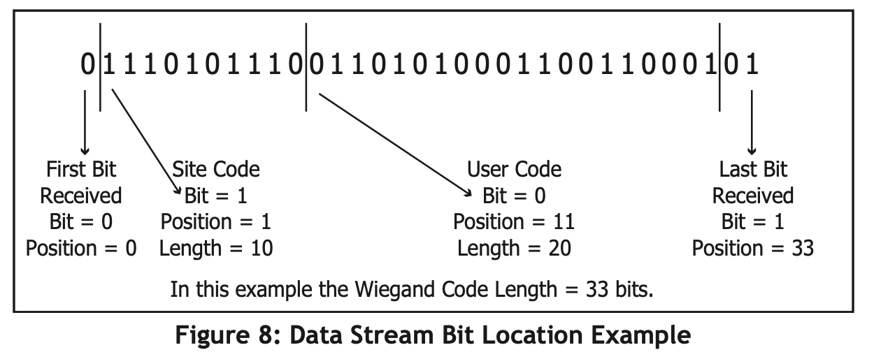
When using a custom credential, enter the total number of bits to be received in Wiegand code including parity bits. Press any top row Select key to enter a number between 0-255 to equal the number of bits. Default is 45 bits.
Typically, an access card contains data bits for a site code, a user code, and start/stop/ parity bits. The starting position location and code length must be determined and programmed into the keypad.