The JamAlert module is a cellular frequency jamming detector and includes the following features:
- Two onboard outputs that can be connected to zones on a panel or used to trigger peripheral devices
- An LED to alert when jamming is detected
- A testing mode to ensure the module is properly detecting frequencies
Select a Location
Install the module away from metal objects and at least 4 to 5 ft. away from any high RF-emitting devices, including high-powered wireless receivers, Wi-Fi routers, and cellular signal boosters, to ensure proper frequency detection. Do not mount the module inside or on a control panel metal enclosure. Mounting the module on or near metal surfaces impairs cellular jamming detection performance.
Follow the guidelines below to choose the best installation for the JamAlert:
Standard Coverage: Install the module at least 15 ft away from the panel or cellular communicator.
Enhanced Coverage: Install the module by likely entry points, such as the front door, back door, or glass doors. Avoid placing the module next to concrete walls. For high-security installations, create a perimeter by spacing each JamAlert approximately 30 ft apart.
Mount the Module
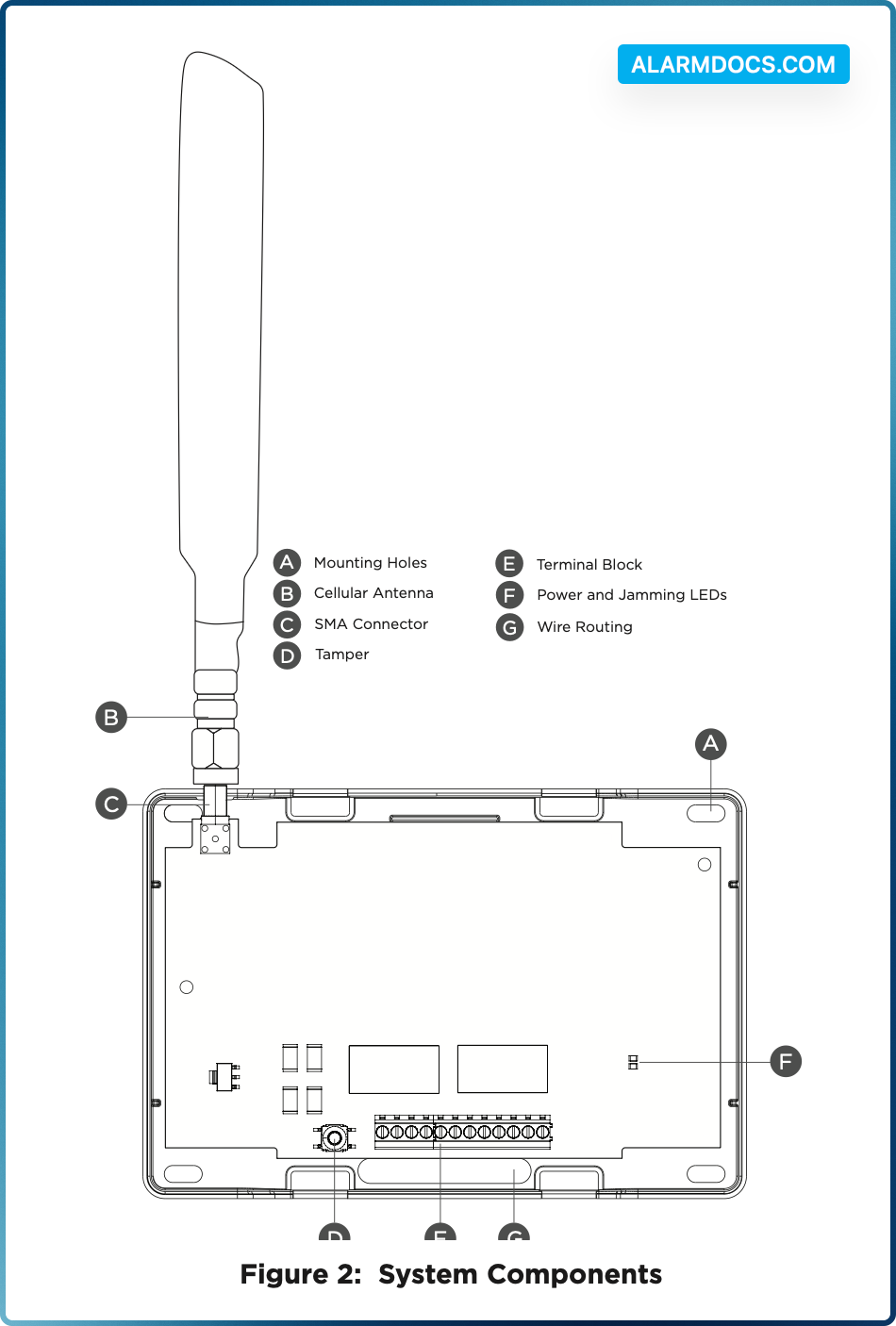
The module should be mounted to a wall using the included #6 screws in the mounting holes. See Figure 2. Mount the module in a secure, dry place to protect the module from damage due to tampering or the elements. It is not necessary to remove the PCB when installing the module.
Wire the Module
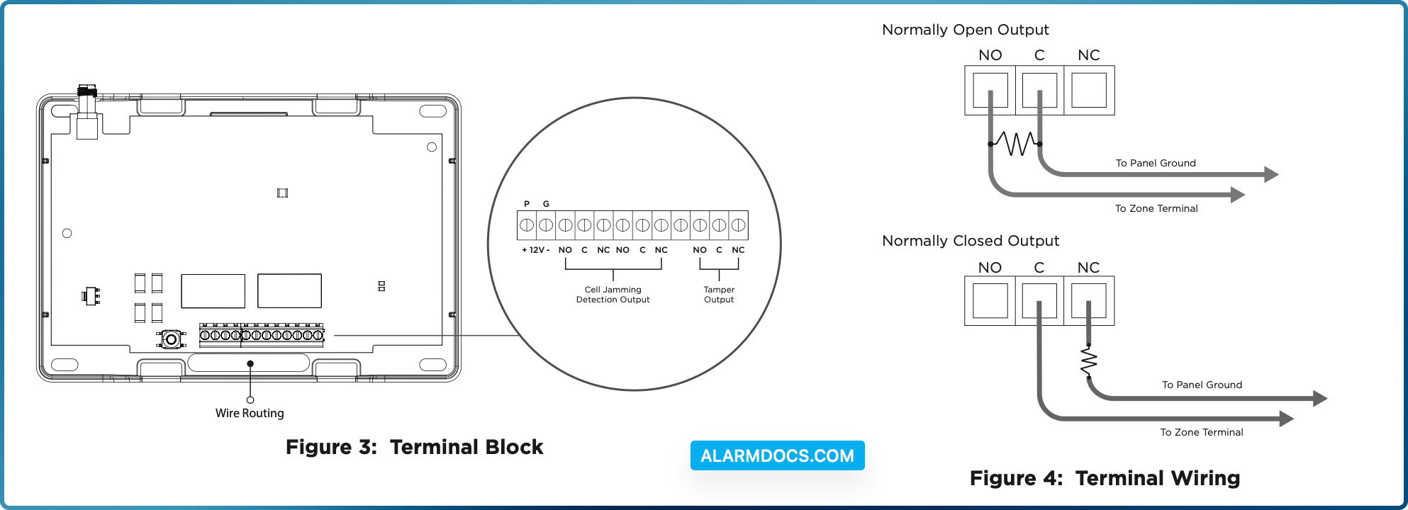
Use 18 to 22 gauge wire when wiring the module. When routing wires, ensure they do not interfere with the tamper switch. Refer to Figure 3 and Figure 4.
1. Use a wire to connect the module’s +12V (positive) terminal to terminal 7 on the DMP panel. Use another wire to connect the module’s -12V (negative) terminal to terminal 10 on the DMP panel.
2. On the cell jamming detection output, use a wire to connect the NO terminal to any zone on the panel. Use another wire to connect the C terminal to the panel ground.
3. On the tamper output, use a wire to connect the C terminal to any zone on the panel. Use another wire to connect the NC terminal to the panel ground. Use a 1k Ohm EOL resistor on the wire connected to the NC terminal.
Connect the Antenna
- Place the antenna onto the SMA connector. Refer to Figure 2.
- Twist the antenna clockwise until it is securely tightened.
- Carefully place the housing cover back on the mounted base. Ensure not to damage any PCB components when removing or replacing the housing cover.
PROGRAM THE PANEL
Refer to the compatible panel programming guide for full programming information.
At the Keypad
After completing each step, press CMD to advance to the next prompt. To program the JamAlert to a DMP panel for jamming detection and tamper detection at the keypad, complete the following steps:
- 1. Reset the panel. At a keypad, enter 6653 (PROG) to access the PROGRAMMER menu.
- 2. At ZONE INFORMATION, enter the zone number for the cell jamming detection output.
- 3. At *UNUSED*, enter a name for the zone.
- 4. Select a ZONE TYPE for the cell jamming detection output.
- 5. At NEXT ZONE, select YES.
- 6. Enter the zone number for the tamper output.
- 7. At *UNUSED*, enter a name for the zone.
- 8. Select a ZONE TYPE for the tamper output.
- 9. Press CMD until STOP displays. Press a top row select key or area to save programming.
Dealer Admin
To program the JamAlert to a DMP panel for jamming detection and tamper detection on Dealer Admin, complete the following steps:
- 1. Log in to Dealer Admin (dealer.securecomwireless.com).
- 2. Select Customers, then select the System Name you want to program the JamAlert zones for.
- 3. Select Programming, then select Zone Information.
- 4. Select + Add Zone. The Zone Number automatically populates. Update the zone number if needed.
- 5. Enter a Zone Name and select a Zone Type in the drop-down menu for the cell jamming detection output.
- 6. Configure additional options as needed.
- 7. Select + Add Zone to create another zone. The Zone Number automatically populates. Update the zone number if needed.
- 8. Enter a Zone Name and Zone Type for the tamper output.
- 9. Configure additional options as needed.
- 10. At the top of the screen, select Send All Changes.
Tamper
The JamAlert module includes a wall and case tamper. The case tamper is pressed when the cover of the module is secured onto the enclosure. The wall tamper is pressed when the back of the cover is mounted onto a wall. When the cover is removed or the module is removed from the wall, the module sends a tamper trouble message to the monitoring center.
Module Operation
When cell frequency jamming is detected, the onboard output is activated and sends an alarm to the panel. In addition, if cell jamming is detected, the LED lights red. If power is on, the LED lights green.
Testing Mode
JamAlert uses a local testing operation to ensure the module is properly detecting frequencies. To enter testing mode, complete the following steps:
- 1. Ensure the JamAlert is in its housing and the back case tamper is satisfied (pressed).
- 2. Disconnect the antenna, then ensure the JamAlert is powered on. Refer to Wire the Module for more information about powering the JamAlert.
- 3. Press the tamper button at least 4 times in a row quickly to enter testing mode.
- 4. Connect the antenna to automatically trigger the detection mode. When the device detects a frequency, the LED lights solid red.
- 5. To exit testing mode, power cycle the device or press and hold the tamper button for more than 5 seconds. The LED flashes green 3 times to confirm you have exited testing mode.
Compatibility
- XTL Series Control Panels
- XT Series Control Panels
- XF6 Series Control Panels
- XR Series Control Panels
- TMSentry Control Panels
- Com Series Communicators