Models SD365 and SD365-IV are plug-in type smoke sensors that combine a photoelectronic sensing chamber with addressable-analog communications. The sensors transmit an analog representation of smoke density over a communication line to a control panel. Rotary dial switches are provided for setting the sensor’s address.
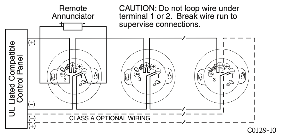
Two LEDs on the sensor are controlled by the panel to indicate sensor status. An output is provided for connection to an optional remote LED annunciator (P/N RA100Z).
Fire-Lite panels offer different features sets across different models. As a result, certain features of the photoelectric sensors may be available on some control panels, but not on others. SD365 will support only LiteSpeed® protocol mode. SD365-IV will support either LiteSpeed or CLIP (Classic Loop Interface Protocol) mode. The possible features available if supported by the control panel are:
- The sensor’s LEDs can operate in three ways—on, off, and blinking–and they can be set to red, green, or amber. This is controlled by the panel.
- The remote output may be synchronized to the LED operation or con- trolled independent of the LEDs.
- Devices are point addressable up to 159 addresses.
Please refer to the operation manual for the UL listed control panel for specific operation. The photoelectric sensors require compatible addressable com- munications to function properly. Connect these sensors to listed-compatible control panels only.
SPACING
Fire-Lite recommends spacing sensors in compliance with NFPA 72. In low air flow applications with smooth ceilings, space sensors 30 feet apart (9.1 m). For specific information regarding sensor spacing, placement, and special ap- plications, refer to NFPA 72 or the System Smoke Detector Application Guide, available from Fire-Lite.
WIRING GUIDE
All wiring must be installed in compliance with the National Electrical Code, applicable local codes, and any special requirements of the Authority Having Jurisdiction. Proper wire gauges should be used. The installation wires should be color-coded to limit wiring mistakes and ease system troubleshooting. Im- proper connections will prevent a system from responding properly in the event of a fire.
Remove power from the communication line before installing sensors.
- Wire the sensor base (supplied separately) as shown in the wiring diagram. (See Figure 2.)
- Set the desired address on the sensor address switches. (See Figure 1.)
- Install the sensor into the sensor base. Push the sensor into the base while turning it clockwise to secure it in place.
- After all sensors have been installed, apply power to the control panel and activate the communication line.
- Test the sensor(s) as described in the TESTING section of this manual.
FIGURE 2. WIRING DIAGRAM:
TAMPER-RESISTANCE
Intelligent photoelectric smoke sensors include a tamper-resistant capability that prevents their removal from the base without the use of a tool.
TESTING
Before testing, notify the proper authorities that the system is undergoing maintenance, and will temporarily be out of service. Disable the system to prevent unwanted alarms.
All sensors must be tested after installation and periodically thereafter. Testing methods must satisfy the Authority Having Jurisdiction (AHJ). Sensors offer maximum performance when tested and maintained in compliance with NFPA 72.
The sensor can be tested in the following ways:
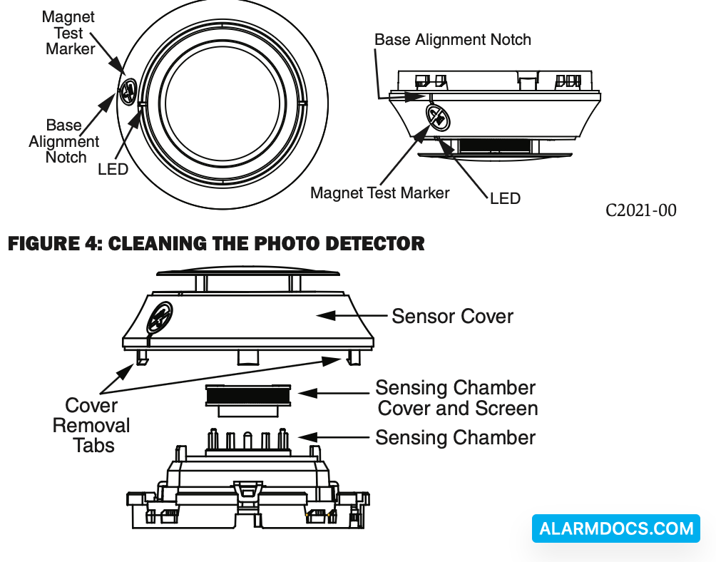
A. Functional: Magnet Test (P/N M02-04-01 or M02-09-00)
This sensor can be functionally tested with a test magnet. The test magnet electronically simulates smoke in the sensing chamber, testing the sensor electronics and connections to the control panel.
- Hold the test magnet in the magnet test area as shown in Figure 3.
- The sensor should alarm the panel.
Two LEDs on the sensor are controlled by the panel to indicate sensor status. Coded signals, transmitted from the panel, can cause the LEDs to blink, latch on, or latch off. Refer to the control panel technical documentation for sensor LED status operation and expected delay to alarm.
B. Smoke Entry
Sensitivity readings are available through the FACP. Refer to the manufacturer’s published instructions for proper use.
Additionally, canned aerosol simulated smoke (canned smoke agent) may be used for smoke entry testing of the smoke detector. Tested and approved aerosol smoke products are:
| Manufacturer | Model |
| HSI Fire & Safety | 25S, 30S (PURCHECK) |
| SDi | SMOKE CENTURIAN, SOLOA4, SMOKESABRE. TRUTEST |
| No Climb | TESTIFIRE 2000 |
When used properly, the canned smoke agent will cause the smoke detector to go into alarm.
When testing is complete, restore the system to normal operation and notify the proper authorities that the system is back in operation.
SPECIAL NOTE REGARDING SMOKE DETECTOR GUARDS
Smoke detectors are not to be used with detector guards unless the combination has been evaluated and found suitable for that purpose.
FIGURE 3: FEATURES OF THE PHOTO DETECTOR
When configured at the fire alarm control panel, this detector is capable of op- erating in a special application mode such that it has a higher sensitivity than is normally allowed by UL 268 for areas where early warning is important. In this mode, the detector does not comply with the Cooking Nuisance Smoke Test. Detectors (Sampling ports) set to the special application mode are not suitable for use in areas where cooking appliances may be used. If cooking appliances are used within the protected space, a normal application detector or normal application mode must be used for that area.
Special application mode is not for general use and the detector may be more prone to false alarms if used in unsuitable environments. While no list is all-inclusive, some examples of unsuitable environments for special applica- tion mode are areas with airborne particulate or aerosols including sawing, drilling, and grinding operations, textile or agricultural processing, or areas with engines that are not vented to the outside. A complete list of aerosol and particulate sources is available in the Annex of NFPA 72.
Suitable environments for special application mode could include early warning for hospitals, museums, assisted living and other areas that do not have airborne particulate or aerosols.