XT Series Control Panels
- Open the panel enclosure, set the reset jumper, and remove power from the panel.
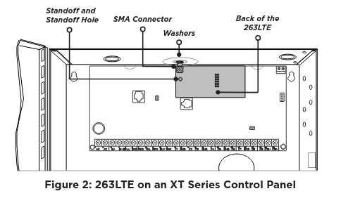
- Insert the included standoff into the panelstandoff hole.
- Align the 263LTE SMA antenna connector with the antenna hole in the top of the panel
enclosure, place one washer around the connector, and secure it on the 12-pin cell module connector. See Figure 2.
Align the 263LTE standoff hole with the standoff already placed in the panel and snap it into place.
XR and XF6 Series Control Panels
- Open the panel enclosure, set the reset jumper, and remove power from the panel.
- Insert the included standoff into the panel standoff hole.
- Secure the 263LTE on the 12-pin cell module connector. See Figure 3.
- Align the 263LTE standoff hole with the standoff already placed in the panel and snap it into place.

CONNECT THE ANTENNA
XT Series Control Panels
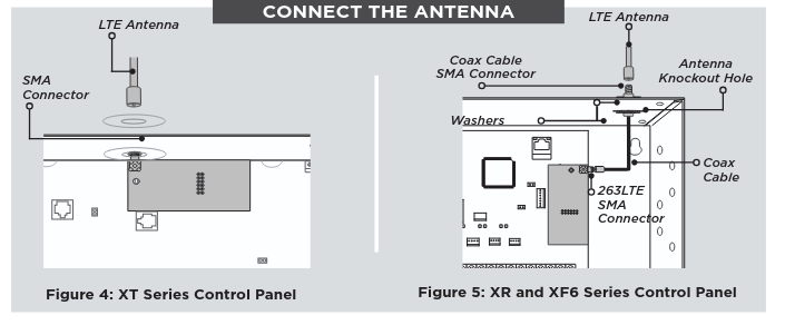
- If installing an XT50 or XT75, place the second washer around the 263LTE SMA connector and connect it to the included antenna at the hole in the top of the panel.
- Connect the 263LTE SMA connector to the included antenna at the hole in the top of the panel. See Figure 4.
XR and XF6 Series Control Panels
- Attach one end of the included coax cable to the 263LTE SMA connector.
- Position one washer onto the other end of the coax cable and push the threaded end through the antenna knockout hole.
- Position the second washer onto the threaded end that extends through the antenna knockout hole and secure the nut.
- Attach the included LTE antenna to the coax cable SMA connector. See Figure 5.
ACTIVATE THE 263LTE
Before power is reapplied to the panel, cellular service needs to be activated. The 263LTE comes ready for activation with SecureComTM Wireless, LLC. Use Dealer AdminTM (dealer.securecomwireless.com) or call DMP Customer Service (1-866-266-2826) to activate the 263LTE.
Dealer Admin Activation
- Navigate to the Dealer Admin site (dealer.securecomwireless.com).
- Go to Customers and select a customer.
- In Systems, select the Add icon.
- Enter a System Name and choose a System Type.
- In Connection Type, select Cellular or EASYconnect + Cell Backup.
- In SIM Number, enter the SIM number and select Get Status.
- Select Activate.
- In Account Number, enter the system’s receiver number followed by the account
number. - Select a Rate Plan for the 263LTE.
- Enter the panel Serial Number.
- To confirm proper communication, select Test Connection.
- A dialog box displays to ask if you want to perform initial connection to the panel. Select Yes.
- Configure additional options as needed, then select Save at the top of the page.
TEST THE 263LTE
The panel provides a diagnostic function to test the communication integrity and cellular signal strength of the 263LTE to the nearest tower for the cellular carrier. To use the diagnostic function, reset the panel, enter 2313 (DIAG), and press CMD.
Carrier Selection
This option is only available when DualSIM is active. In the event that remote connectivity is unavailable, carrier options can be manually switched on the keypad. To select a single carrier, press ATT or VZW. To use DualSIM operation, select BOTH.
Signal Strength Test
If DualSIM is activated, the panel automatically selects a primary carrier (AT&T or Verizon) when the panel is turned on. Once the primary is established, the panel tests the signal strength of the primary every hour. During the test, if the primary’s signal drops by 10db or more, the panel then tests the backup carrier. If the backup has a stronger signal, it becomes the new primary. Every five hours, the panel automatically tests the backup’s signal strength to determine the stronger signal.
Communication Status
This option tests the individual components of cellular or wireless network communication. To test the communication status, complete the following steps:
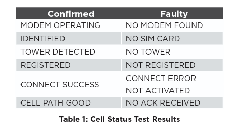
Select CELL STATUS from the Diagnostic menu. Possible test results are shown in Table 1.
Select YES to continue through the remaining component tests or select NO to stop testing and return to CELL STATUS.