The X1 Series is a cloud‑based access door controller that is fully programmed in Dealer Admin™ and maintained in Virtual Keypad™. This guide will cover mounting the door controller, wiring devices to the door controller, configuring network options, applying power, programming the door controller in Dealer Admin, and testing the door controller.
Door Controller Power

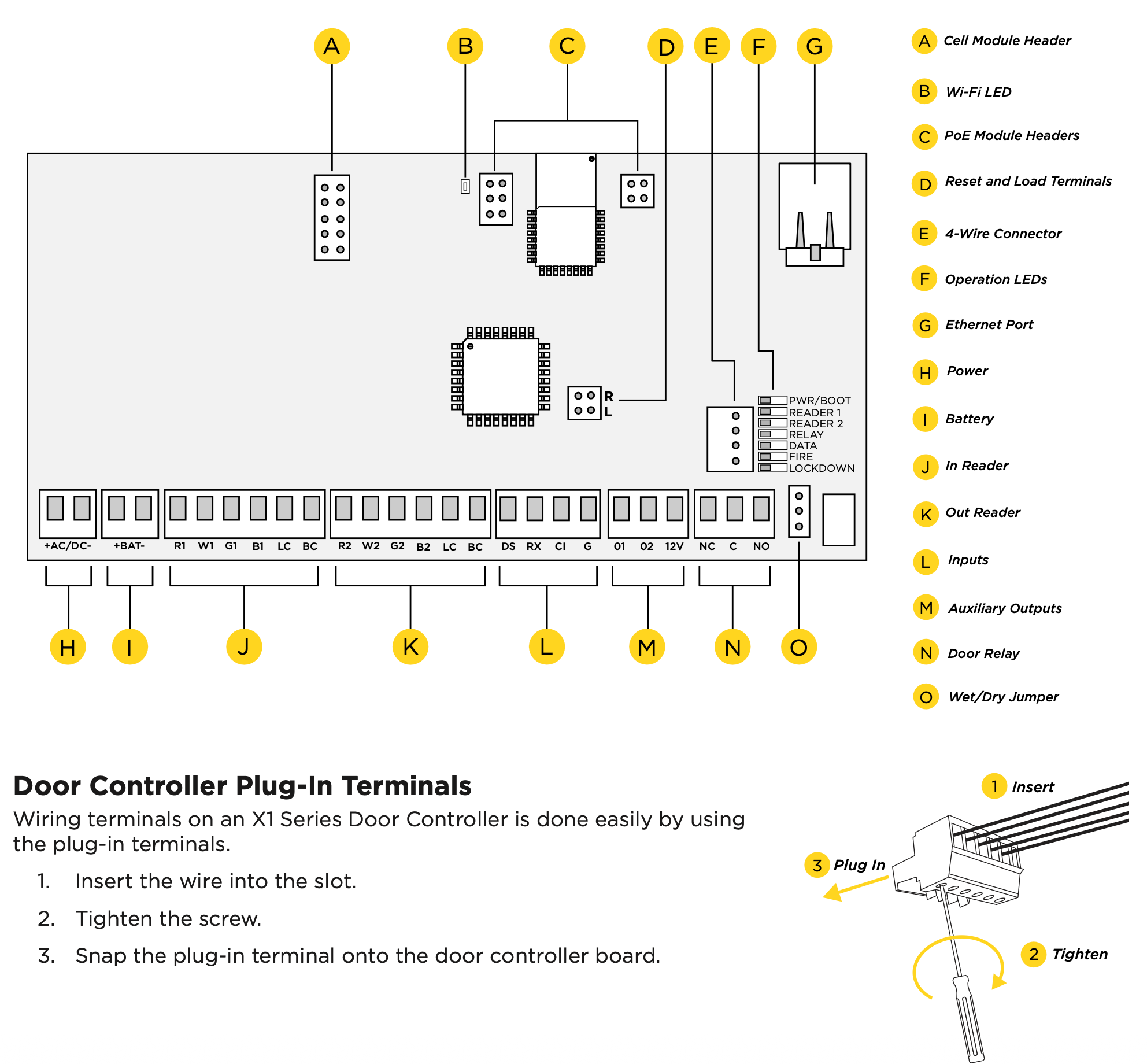
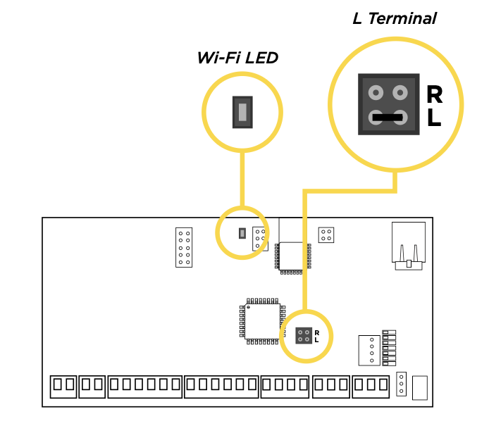
Door Controller PCB Components
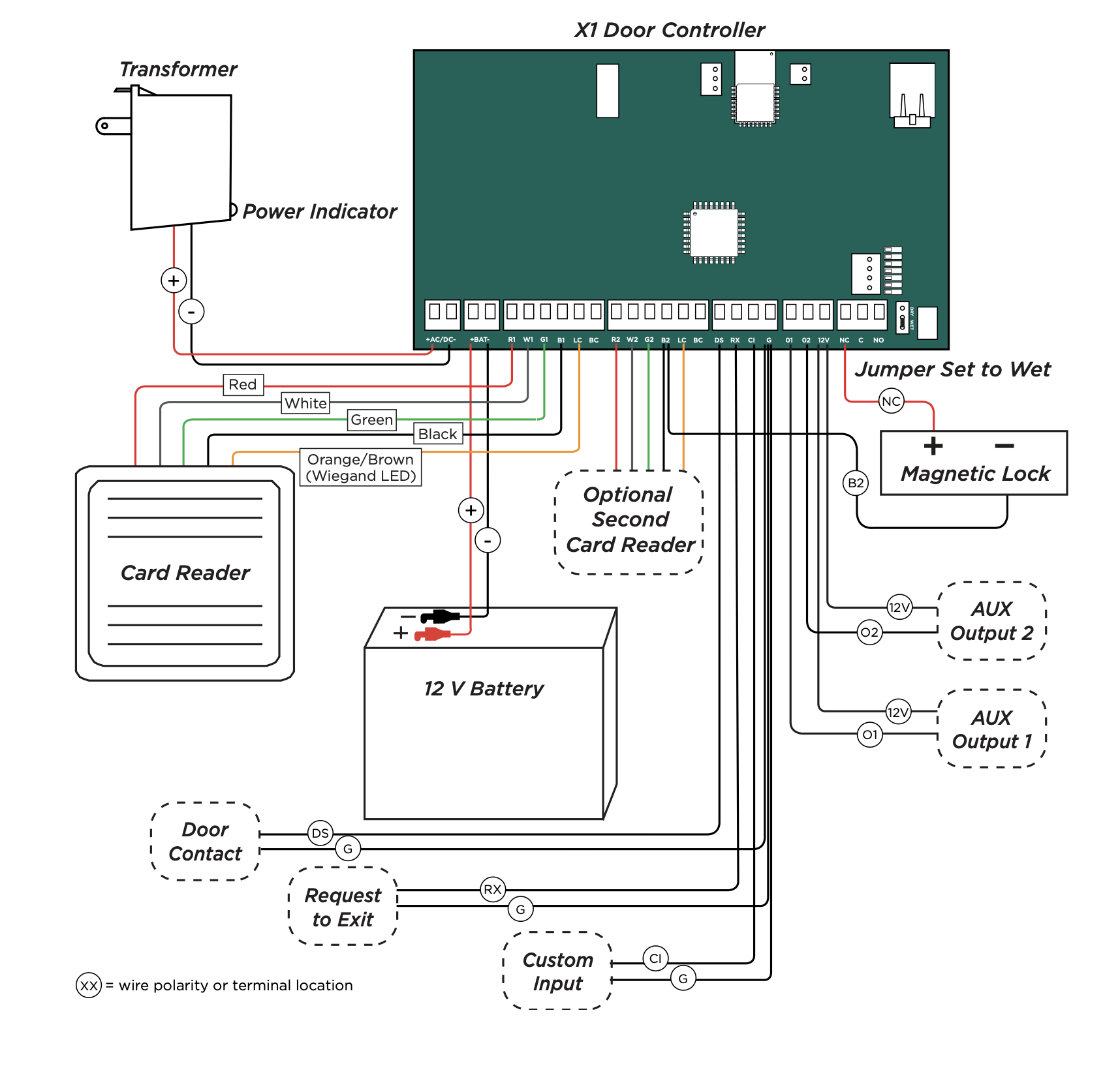
Refer to the diagram below throughout the installation.
PRE-INSTALLATION
If the controller has been connected to a network prior to final installation, while connected to the network delete the controller’s programming from Dealer Admin. Wait at least three minutes before disconnecting. This allows the controller to initialize and return to factory settings.
MOUNT THE DOOR CONTROLLER
The metal enclosure for the X1 Series must be mounted directly to a wall, backboard, or other flat surface in a secure, dry place to protect the door controller from damage. Do not remove the PCB from the enclosure.
CONNECT A CARD READER
The X1 Series provides connections for 2 readers. The first reader is designated for the In Reader and the second is designated for the Out Reader.
The X1 Series also provides direct 12 VDC output to the reader on the RED terminal connection.
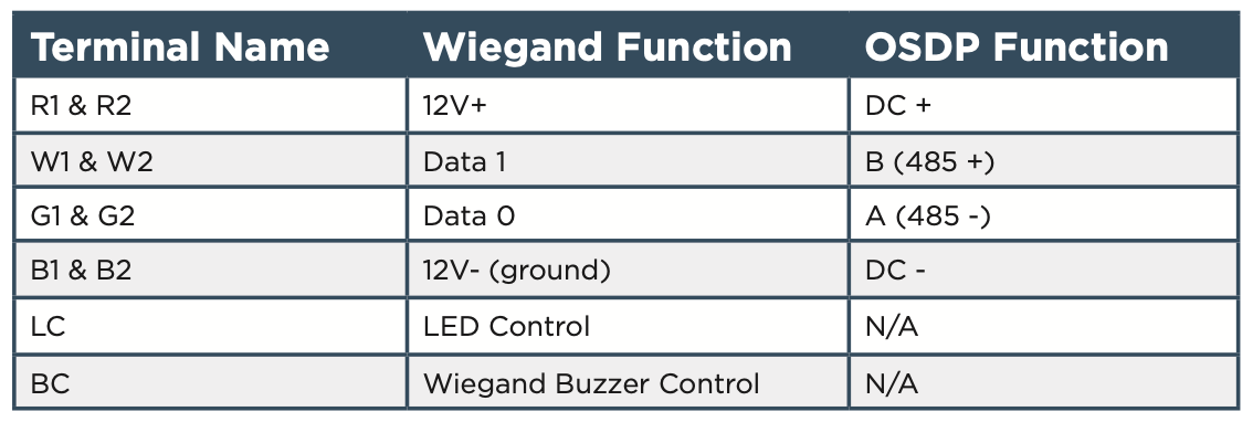
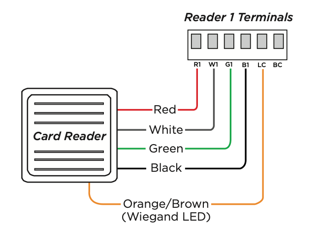
Connect a Wiegand Card Reader
- Connect the red wire (12 VDC) to terminal R1.
- Connect the white wire (Data One) to W1.
- Connect the green wire (Data Zero) to G1, black (ground) to B1.
- Connect the orange or brown wire to LC.
Connect an OSDP Card Reader
- For data transmission, connect the A wire (485 –) to the G1 terminal and the B wire (485 +) to the W1 terminal.
- For reader power, connect the red wire (DC + ) to the R1 terminal and the black wire (DC –) to the B1 terminal.
Optional Second Card Reader
For an out reader, connect the red, white, green, and black wires to the Reader 2 terminals: R2, W2, G2, and B2. Connect the orange/brown wire to LC.
If using only one reader, it must be connected to reader 1.
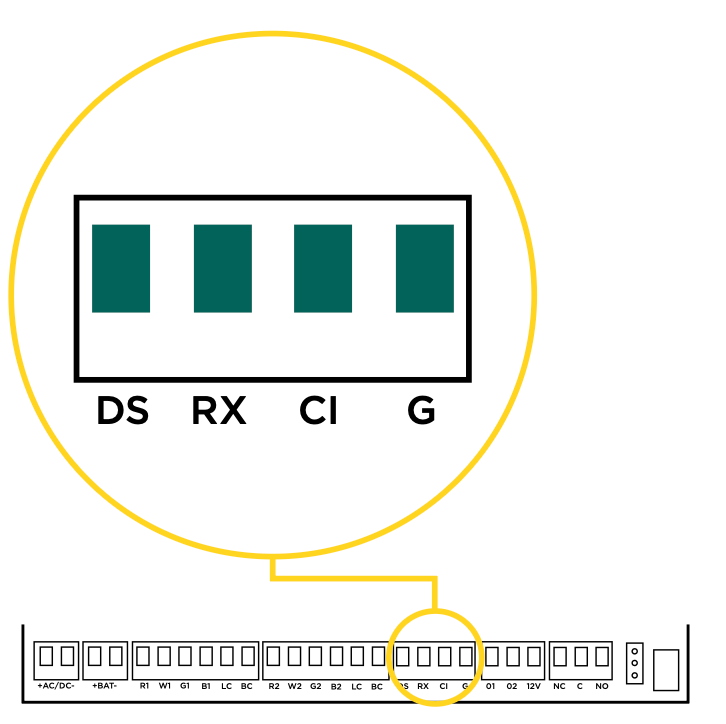
WIRE THE INPUTS
Door Switch (DS)
Connect a door contact or door position switch to indicate the status of the door, whether it is open or closed. Use this terminal if enabling door prop or door force.
This terminal is a Normally Closed input.
Request to Exit (RX)
Connect a motion sensing device or a mechanical switch to provide RX capability to the door controller. RX can be used to activate the door relay. When activated the RX activates the door lock relay based on the programmed unlock time. Use this terminal if enabling forced door.
This terminal is a Normally Open input.
Custom Input (CI)
This input triggers a rule programmed in Virtual Keypad.
This terminal is a Normally Open input.
Ground (G)
This terminal is the ground for the inputs.
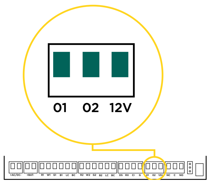
WIRE THE ONBOARD OUTPUTS
Use these switches to ground outputs for local outputs or door alarms such as sounders, lights, or sirens. These are switched ground outputs with an optional constant positive 12 VDC terminal. For example, a sounder could be wired for local indication of a door prop or door force event.
Aux Output 1 & 2 (O1 & O2)
Attach the negative wire of the device here.
The relay contacts must be connected to devices located within 98.5 ft (30m) of the X1.
12V+ (12V)
Attach the positive wire of the device here.
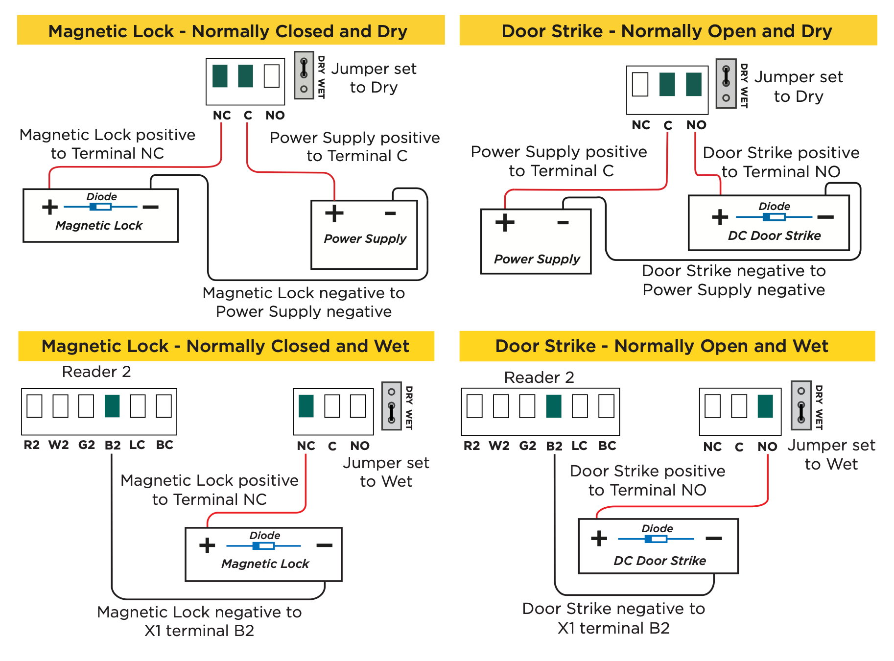
WIRE THE ELECTRONIC LOCK
Form C Relay
The X1 Series provides a Form C (SPDT) relay for controlling locks and other electronically‑controlled barriers. The three relay terminals marked NO C NC allow you to connect the device wiring to the relay for module control.
The Form C relay draws up to 35 mA of current and contacts are rated for 1 Amp (resistive) at 12 VDC. When connecting multiple locks to the Form C relay, the total current for all locks cannot exceed 1 Amp. If the total current for all locks exceeds 1 Amp, problems will arise, it will not work as intended, and an isolation relay will be required.
Diode
Connect the included diode as close to the magnetic lock or door strike as possible to prevent inductive kickback. Observe polarity when connecting the diode.

Wet/Dry Jumper
Putting the jumper on the top two terminals will place it in the dry condition and putting the jumper on the bottom two terminals will place it in the wet condition. When using a dry relay, a power supply is needed to power the lock/strike. When using a wet relay power is already supplied through the relay.
DETERMINE COMMUNICATION
The options in this section are in the DMP‑recommended installation order. If an option is not part of your desired application, move to the next option.
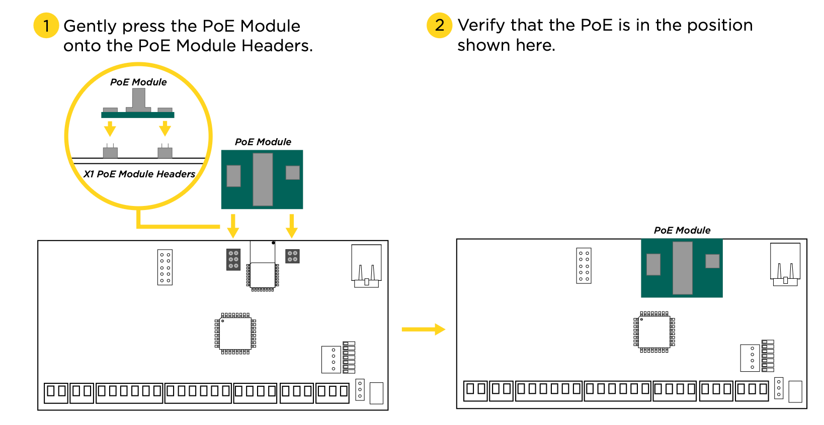
X‑PoE Connection (Optional)
For a PoE connection, gently push the PoE Module onto the X1 PoE Module headers.
DETERMINE COMMUNICATION
The options in this section are in the DMP‑recommended installation order. If an option is not part of your desired application, move to the next option.
X‑PoE Connection (Optional)
For a PoE connection, gently push the PoE Module onto the X1 PoE Module headers.
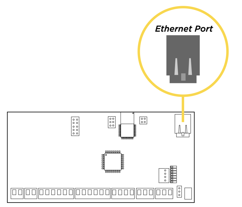
Ethernet Connection
Connect an Ethernet cable from the LAN/WAN connection to the X1 PCB Ethernet port.
Two LEDs are located on the Ethernet port.
- The green LED indicates data is being sent over the network.
- The yellow LED indicates the speed of the transmission. A solid yellow LED indicates the network is connected at 100BASE‑T. A flashing yellow LED indicates the network is connected at 10BASE‑T.
Cellular Connection (Optional)
If the network cable or Wi‑Fi are not connected, cell will be the primary communication.
- Plug the included standoff into the door controller board.
- Carefully insert the antenna connector of the new cell module through the top of the enclosure.
- Plug the cell module onto the standoff.
- Plug the cell module into the cell header.
- Screw on the cell module antenna to the antenna connector with the washer on the outside of the enclosure.
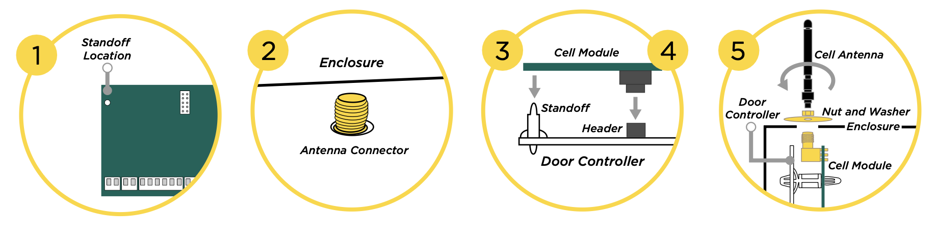
Once connected to an X1, the communicator will automatically register with the cellular carrier upon power up.
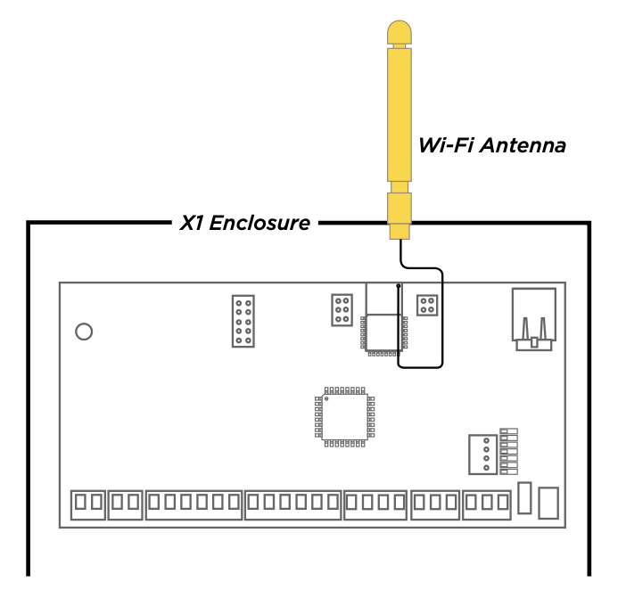
Wi‑Fi Connection
A Wi‑Fi connection or a static IP address must be established after power up. See Wi‑Fi instructions later in this guide.
Wi‑Fi Antenna
The yellow Wi‑Fi antenna connects to the right of the cell antenna on the enclosure.
If the cable has become detached from the X1, simply wire it back onto the Wi-Fi module and run the cable around the module.
Run the Wi-Fi cable to the top of the enclosure as shown here.
INSTALL OPTIONAL OUTPUT MODULE
X1 Output Module PCB Components
Refer to the diagram below throughout the installation.
Mount the X1 Output Module
The metal enclosure for the X1 Output Expansion Module must be mounted to a wall, backboard, or other flat surface within 3 feet of the X1 or X1-8 Door Controller. It is not necessary to remove the PCB when installing the enclosure.
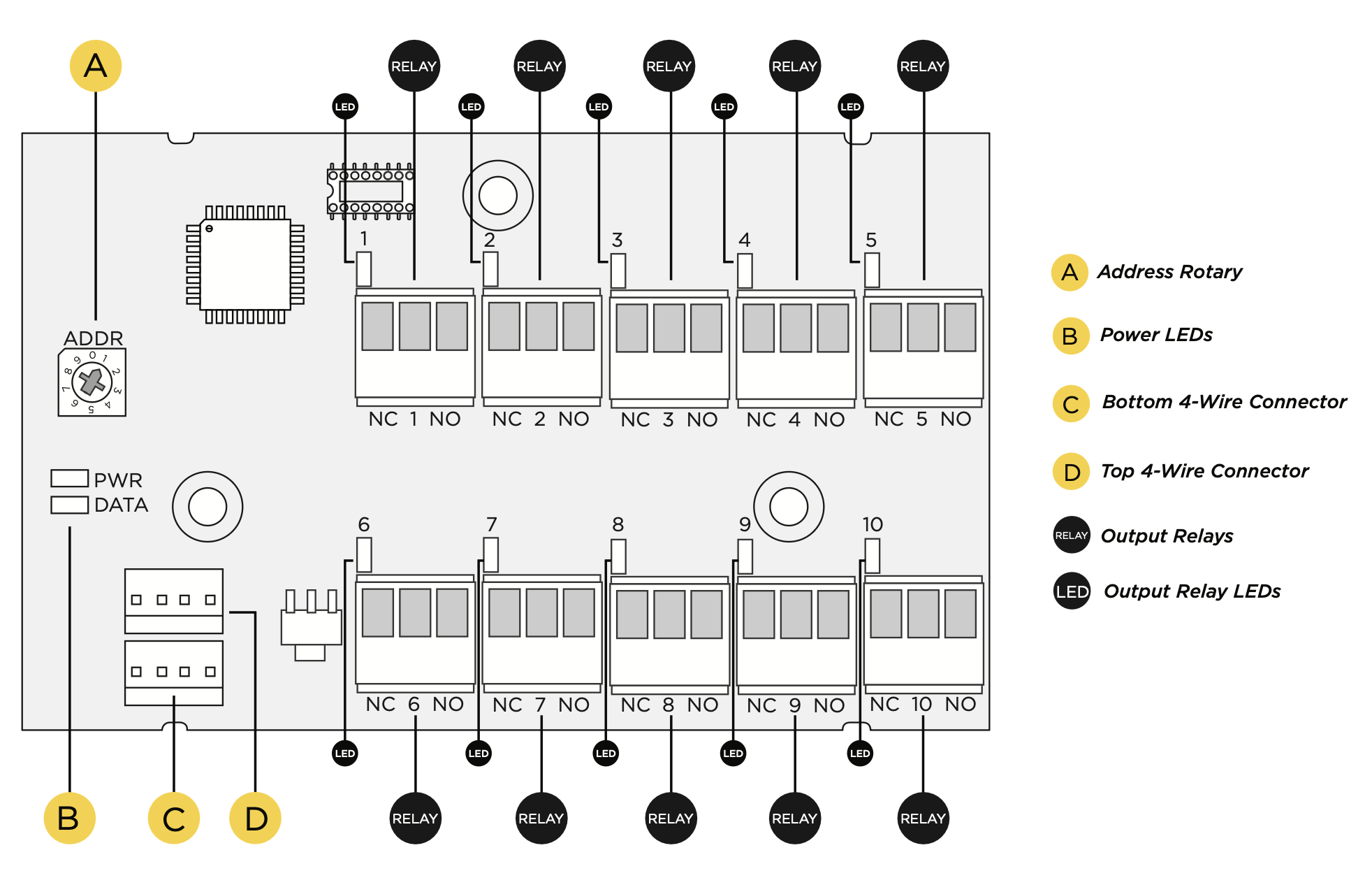
Address the X1 output module
The X1 Output Module (X1-OUT-EXP) has a 1 through 9 addressable rotary dial that is factory defaulted to 1. Additional modules need to be addressed in sequence.
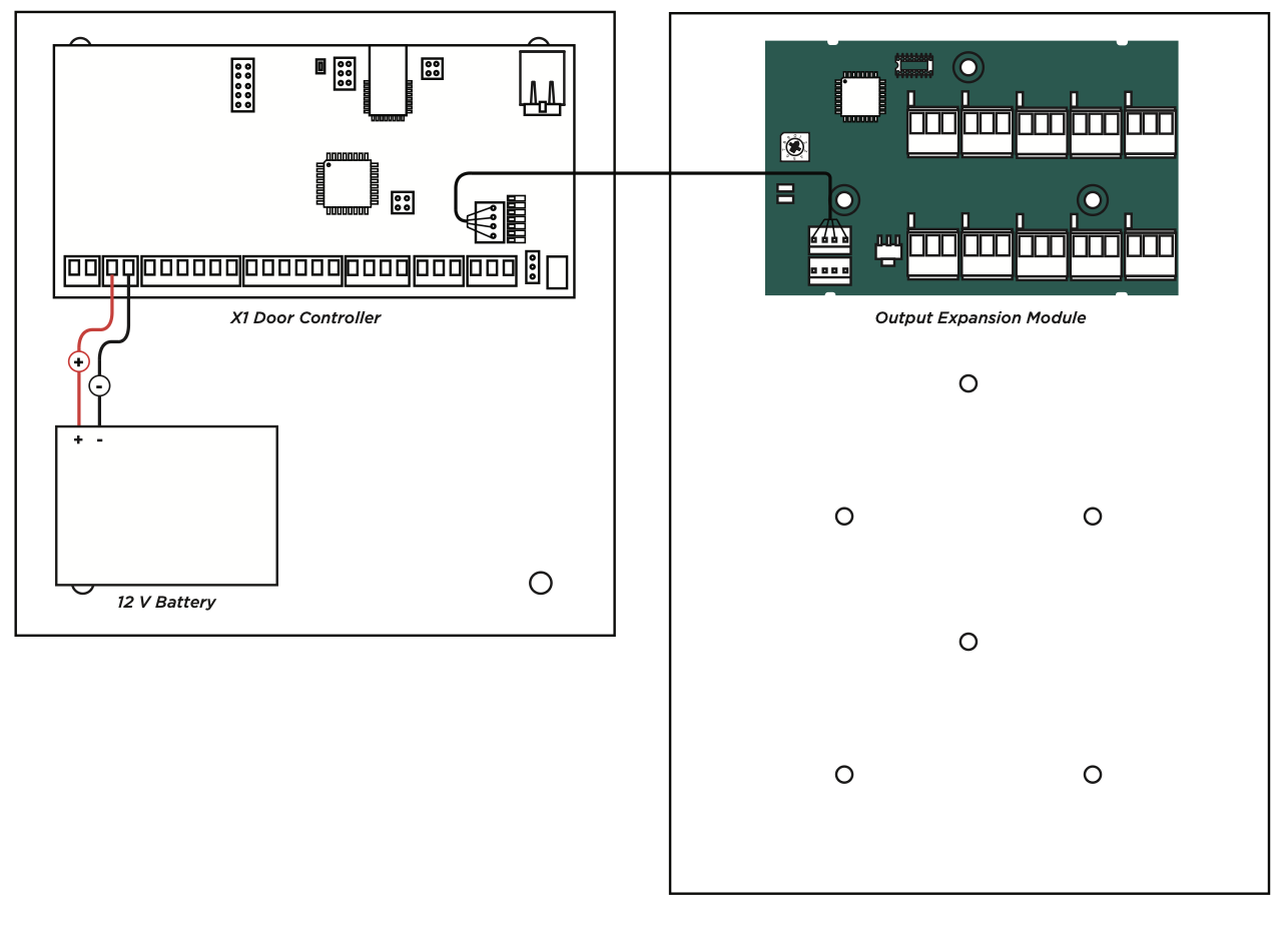
Wire the X1 Output Module
Use the included 4-position harness and enclosure knockouts to connect the top connector on the output 5 4 3 2 6 7 8 1 9 0 module to the connector on the door controller module.
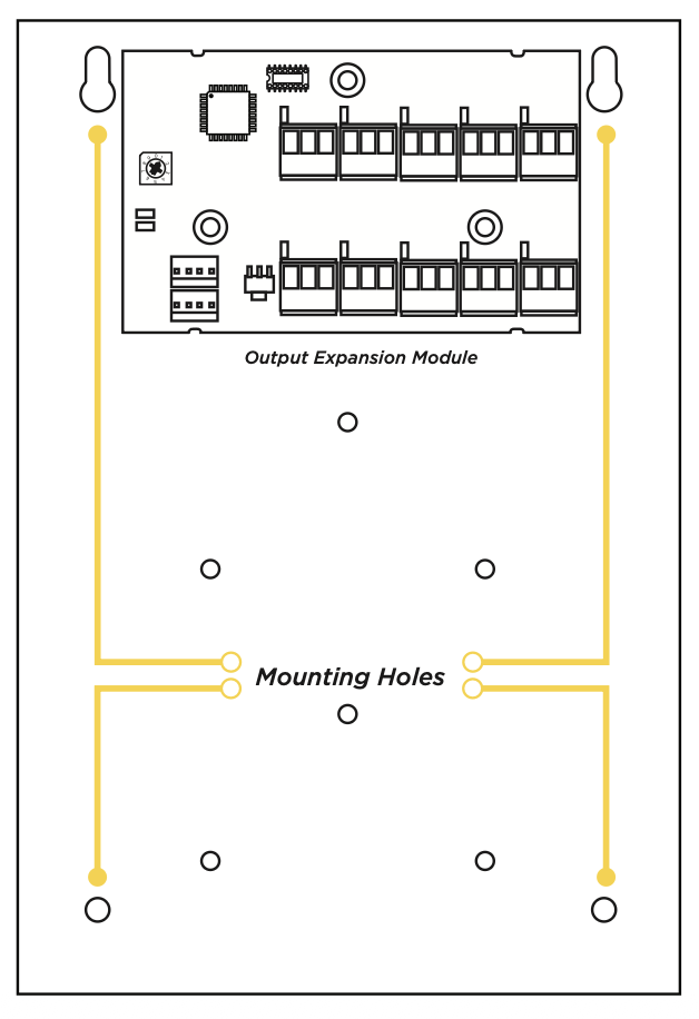
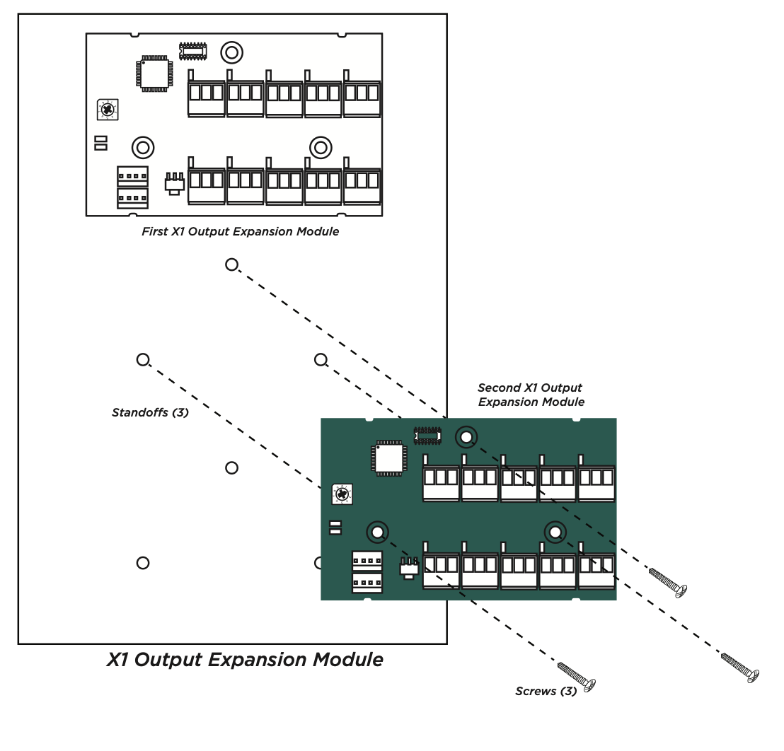
Optional Additional Output Modules
If not installing additional output modules, skip to Step 6 Wire the Outputs.
The metal enclosure for the X1 Output Expansion Module comes with mounting holes for two additional X1 Output Module PCBs. To mount the additional PCB, use the provided standoffs and screw the PCB onto the 3 mounting holes.
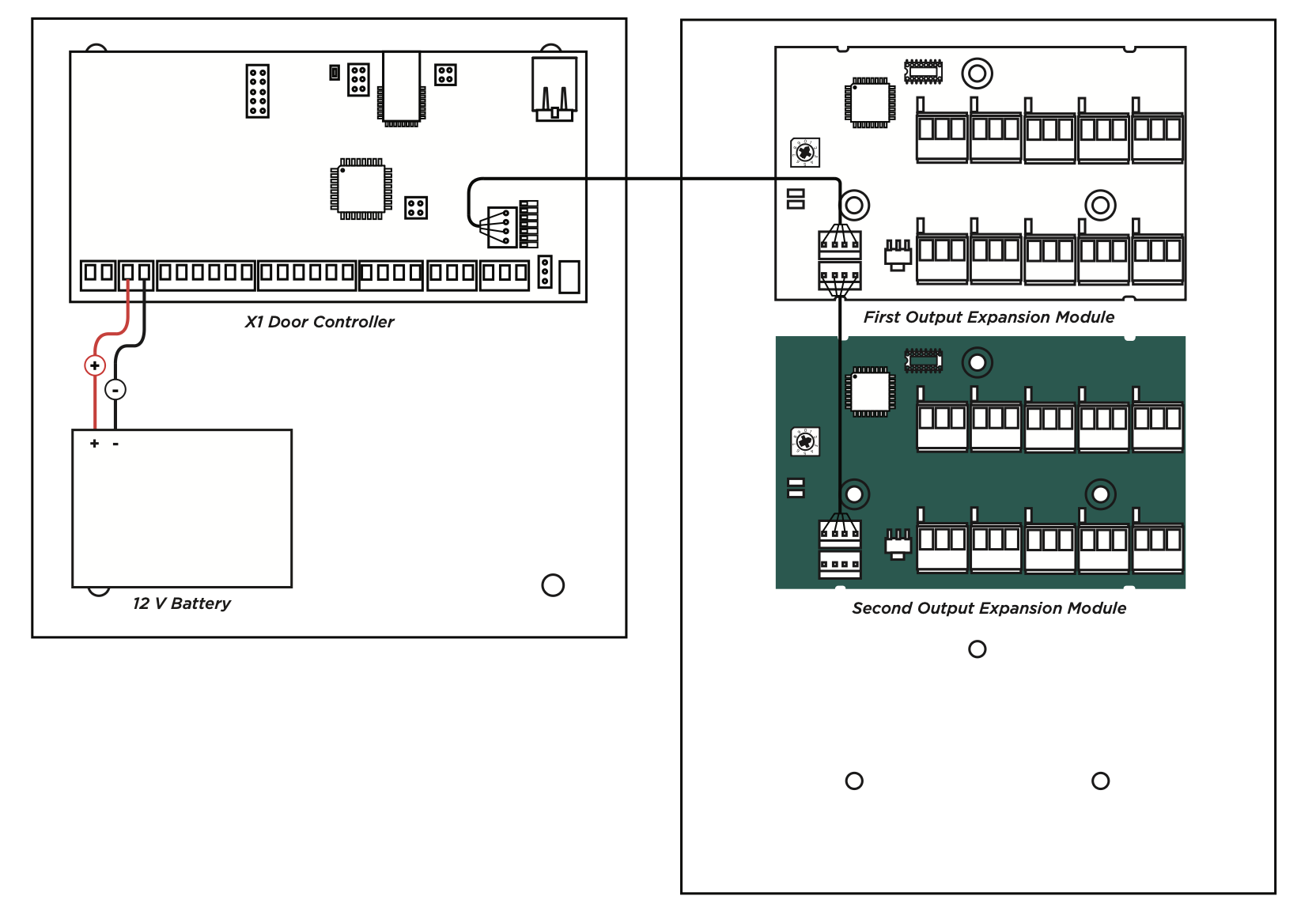
Wire the Optional Additional Modules
If not installing additional output modules, skip to Step 6 Wire the Outputs.
Use the included 4-position harness to connect the top connector on the second output module to the connector on the first output module.
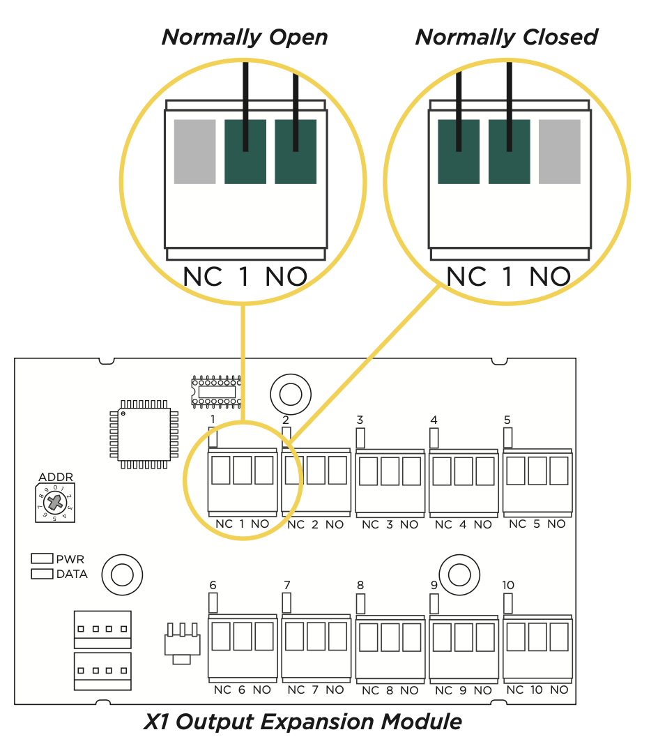
Wire the Outputs
To wire for output control, use the 10 terminals on the output module.
The X1 Series Output Module provides 10 Form C (SPDT) 1 Amp relays for controlling access to 10 outputs. The three relay terminals are labeled for normally open (NO) and normally closed (NC) operation. The center terminal is the common. See figures.The X1 Series Output Module provides 10 Form C (SPDT) 1 Amp relays for controlling access to 10 outputs. The three relay terminals are labeled for normally open (NO) and normally closed (NC) operation. The center terminal is the common. See figures.
APPLY POWER
Wire the Input Power
Connect the transformer wires or external power to terminals 1 and 2 on the X1 PCB. Use no more than 70 ft. of 16 gauge or 40 ft. of 18 gauge wire between the transformer and the X1 PCB.
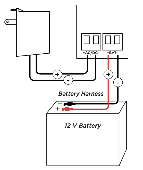
Wire the Battery
Connect the red battery lead to the battery positive terminal. Connect the black battery lead to the negative battery terminal. Observe polarity when connecting the battery.
Wiring Example
The diagram here shows the transformer and the battery wiring. It also shows a possible application with an electronic lock wired normally closed with wet contacts.
MANAGE CONNECTION SETTINGS
During the fifteen minutes after power up, the X1 broadcasts an SSID of DMPX1 followed by the door controller’s serial number.
Depending on the connection type, follow the steps in either the Wi‑Fi, Network, or Cell sections below.
Configure Wi-Fi Settings
- Connect to the X1’s SSID using a cell phone, tablet, or laptop. If using a phone, use only Wi-Fi and disable mobile data. Some phones may try to use the mobile data connection.
- Enter 192.168.1.1 into the URL field.
- In the Wi‑Fi options, enter the customer’s Wi‑Fi network information.
- Select Apply, and the X1 will reset.
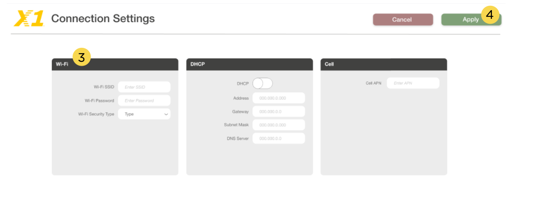
Once the X1 has reset, it will automatically connect to the customer’s network with the updated settings.
Configure Network Settings
- Connect to the X1’s SSID using a cell phone, tablet, or laptop. If using a phone, use only Wi-Fi and disable mobile data. Some phones may try to use the mobile data connection.
- Enter 192.168.1.1 into the URL field.
- In the DHCP options, make edits to the desired fields.
- DHCP: This option is turned on by default.
- Static IP: Turn off DHCP and enter the information in the required fields.
4. Select Apply, and the X1 will reset.
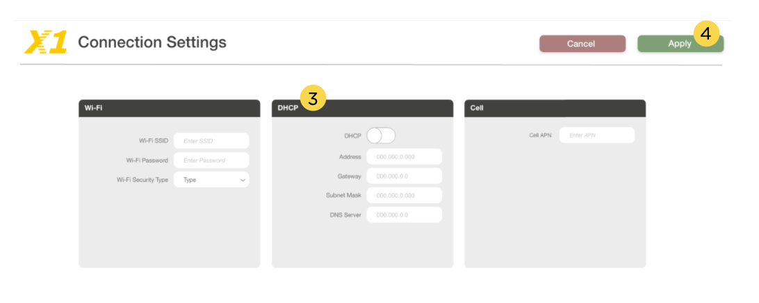
Once the X1 has reset, it will automatically connect to the customer’s network with the updated settings.
Configure Cell Settings
On power up, if using cell, the X1 automatically connects and programming in Dealer Admin can begin.
Troubleshoot SSID Broadcast
If more than fifteen minutes have passed since power up or if the X1 does not broadcast an SSID:
- Short the L terminals for 3 seconds and then place the jumper back on one pin of the L terminal. This will give an additional fifteen minutes of broadcasting.
- Configure the desired connections settings.
To learn how to program X1 in dealer admin. Click Here ..