PROGRAM IN DEALER ADMIN
After you’ve installed the X1 Series Door Controller and configured basic communication settings, follow the steps in each of the following sections to program the door controller in Dealer Admin:
- Sign In to Dealer Admin
- Add a Customer
- Add the X1 Door Controller to a Customer
- Program the X1 Door Controller
- Connect the X1 Door Controller to an XR Series Panel (Optional)
- Add Card Formats
- Add an X1 Output Module (Optional)
- Enable Video Services
- Add an App User
- Log in as Customer
Sign In to Dealer Admin
Go to the Dealer Admin login page. Enter your Email and Password, then press Sign In.
Add a Customer
- At Customers, select + Add.
- Enter the customer’s name and email.
- Enter the customer’s contact information if desired.
- Press Save.
Add the X1 Door Controller to a Customer
- Go to Customers.
- Select a customer to open the Customer Summary.
- In Systems, select + Add.
- Enter a name for the door controller.
- In System Type, select X1.
- Configure billing address and time options as needed.
- Enter the door controller’s serial number.
- Press Save.
Program the X1 Door Controller
If door options don’t open automatically, select the X1 that you want to configure.
- Enter a descriptive name for the door.
- In Strike Time, enter the number of seconds that you want the door to unlock when access is granted.
- In Strike Delay, enter the number of minutes that you want to delay the door unlock when access is granted.
- In Reader Protocol, choose a protocol for this door’s readers: Wiegand or OSDP. For OSDP readers, configure buzzer and LED options. Note: OSDP readers must be either new or factory reset so they can bind properly with the door controller. A unique OSDP secure key is automatically programmed.
- If you have wired any onboard outputs, name them in Onboard Output 1 Name and Onboard Output 2 Name.
- Turn on additional options as needed.
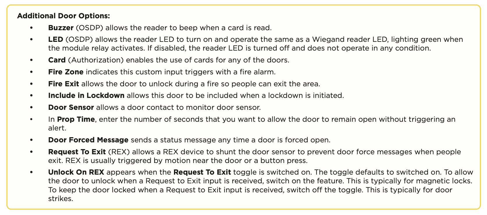
In Dealer Admin, when setting up the controller to be associated with an alarm panel, toggle on Alarm Panel. This displays a drop down menu to select an available output.
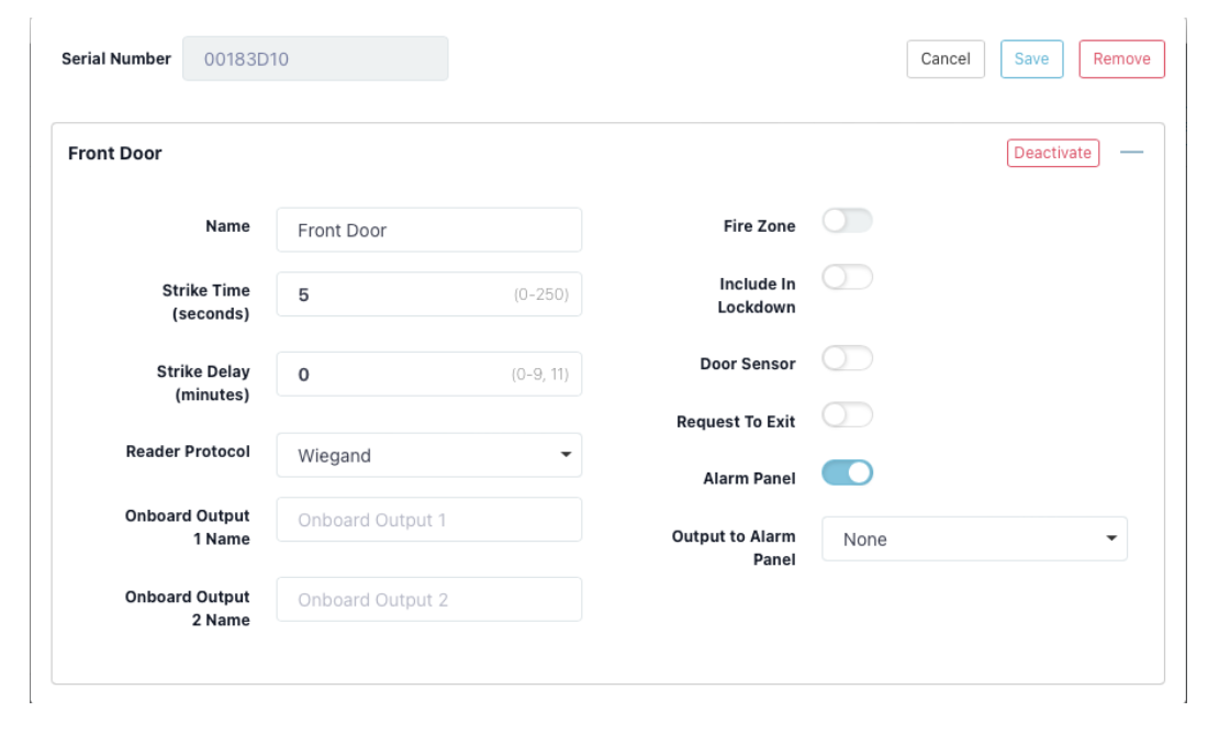
The selected output will be wired to an available zone on the connected alarm panel. The zone must be programmed as an Arming or Keyswitch zone type. Wire an available output from the connected alarm panel to the Custom input of the X1 controller. The output of the connected alarm panel should be programmed as an armed output.
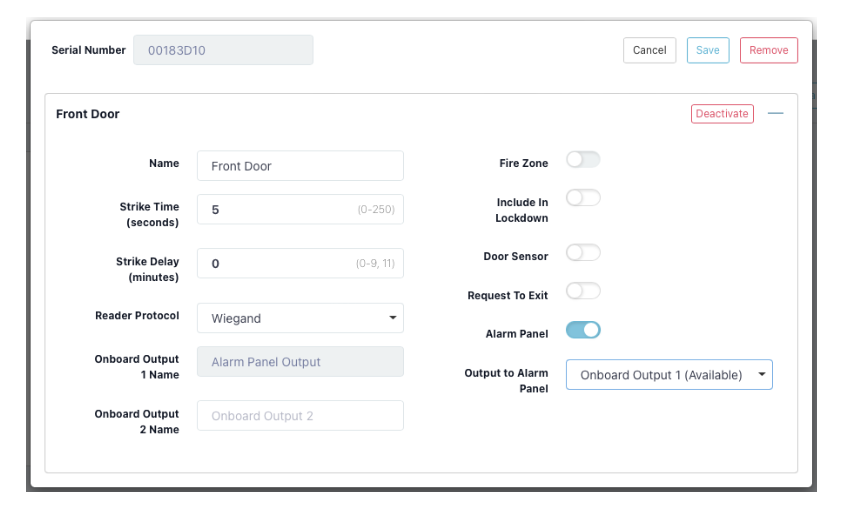
Press Save.
Connect the X1 Door Controller to an XR Series Panel (Optional)
X1 to XR communication allows for sites with an X1 Door Controller and an XR Series panel to communicate over the same network to arm and disarm areas, initiate a fire exit, and initiate a lockdown across the site.
1. Click Edit.
2. At XR Communication, click the toggle to enable the X1 site to be connected to the XR system.
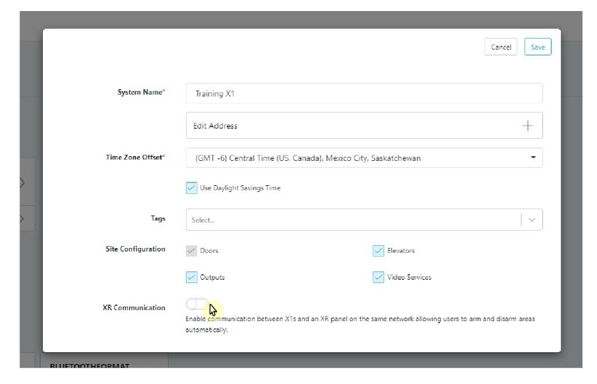
3. At XR Serial Number, enter the serial number of the XR panel you want the X1 site to communicate with.
4. (Optional) At X1 Site Passphrase, click Copy Passphrase. This passphrase is automatically generated and cannot be edited. If the XR panel is already online, then Dealer Admin will automatically program the passphrase in the XR panel.
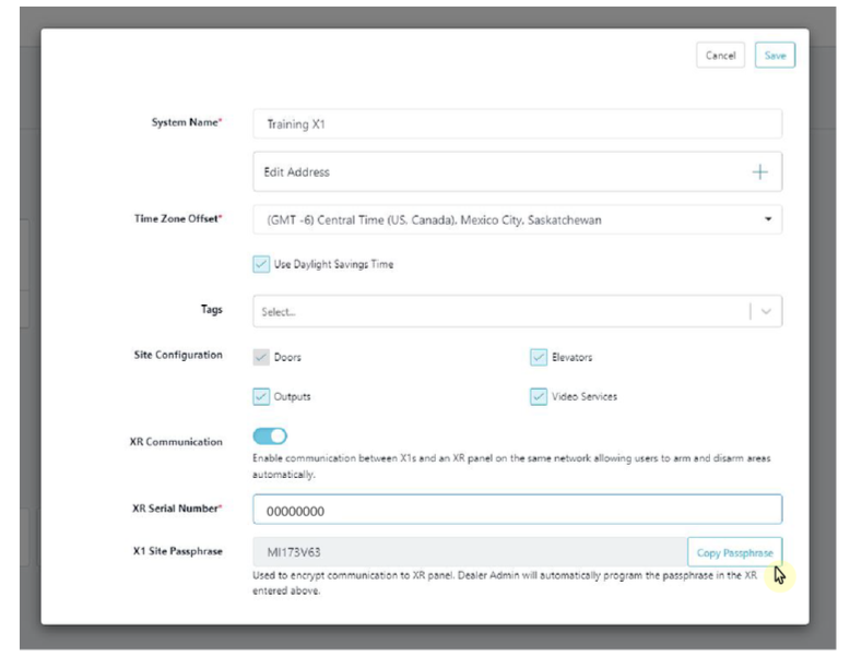
5. Click Save.
Add Card Formats
The first card format for any door is defaulted to DMP. Refer to Card Format Options below when programming card formats.
1. In Card Formats, select + Add.
2. Give the card format a name.
3. Select a card format and configure format settings.
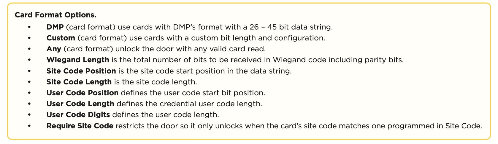
4. Press Save.
5. Go to System Information.
Add an X1 Output Module (Optional)
If your application does not include an X1 Output Module, skip to Enable Video Services.
- Go to System Information.
- Under Outputs, select + Add.
- Select the X1 that the output module is connected to.
- For Output Name, use a descriptive name for the output expansion module’s location,
- For each Relay, name each output that you intend to use. Unnamed outputs will not be programmed.
- Press Save.
Enable Video Services
- In Video Services, select + Add.
- Select the types of cameras or NVRs that you want to enable on the door controller.
- Select any third-party applications that you want to enable on the door controller. This allows users to sign in to their services from Virtual Keypad.
- Press Save.
- Back on the System Information page, select the number of cameras and storage space you require or choose the number of doorbells that you want to add to the door controller.
Add an App User
Adding an app user to an X1 Door Controller automatically adds them as a user in Virtual Keypad.
- Go to Customers.
- Select a customer to open the Customer Summary.
- In the App Users section, select + Add.
- For a user that doesn’t have a Virtual Keypad account, select New. For a user that already has an account, select Existing.
- For a new user, enter their email address. For an existing user, start typing to search for their email and select it from the list.
- Set the user’s authority level to either Administrator to manage multiple door controllers or Standard to manage a single door controller.
- For a new user, enter their first and last name. If you don’t want to generate a random password for the user, clear Create Random Password then manually enter one.
- If you want to email the user video clips, select Email Video Clips.
- Select systems and permissions for the user.
- Press Save.
Log In as a Customer
- Select Login as Customer to log in to Virtual Keypad and view the door controller like a customer would. This adds you to the door controller as a temporary app user with admin privileges without the capability to view video. Your temporary app user expires and is automatically removed from the door controller after 1 hour.
- Go to Groups.
- Select + Add.
- Select the name placeholder and enter a descriptive name for the group.
- In Doors, add the doors that you want group members to have authority to access.
- In Floors, add the floors that you want group members to have authority to access.
- In Access Schedules, choose when group members can access the assigned doors.
- Select permissions for group members.
- Select Save.
- Go to Users.
- Select the user you want to attach the group to.
- Select the group you want the user to have.
- Select Save.
TEST THE DOOR CONTROLLER
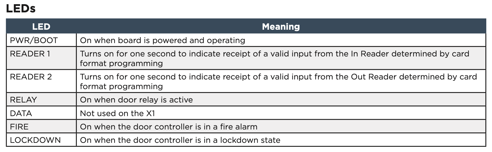
Make sure that the Reader LEDs are on and the door controller’s Power LED is on. If connected to Wi‑Fi, the Wi‑Fi LED is on solid. If connected to network, the Network Port light is blinking. For cell and all communication methods, check that the door controller is communicating with Dealer Admin and Virtual Keypad after Dealer Admin programming is completed.
If using an output module, the each LED is on when the relay is on and off when the relay is off.
ADDITIONAL INFORMATION
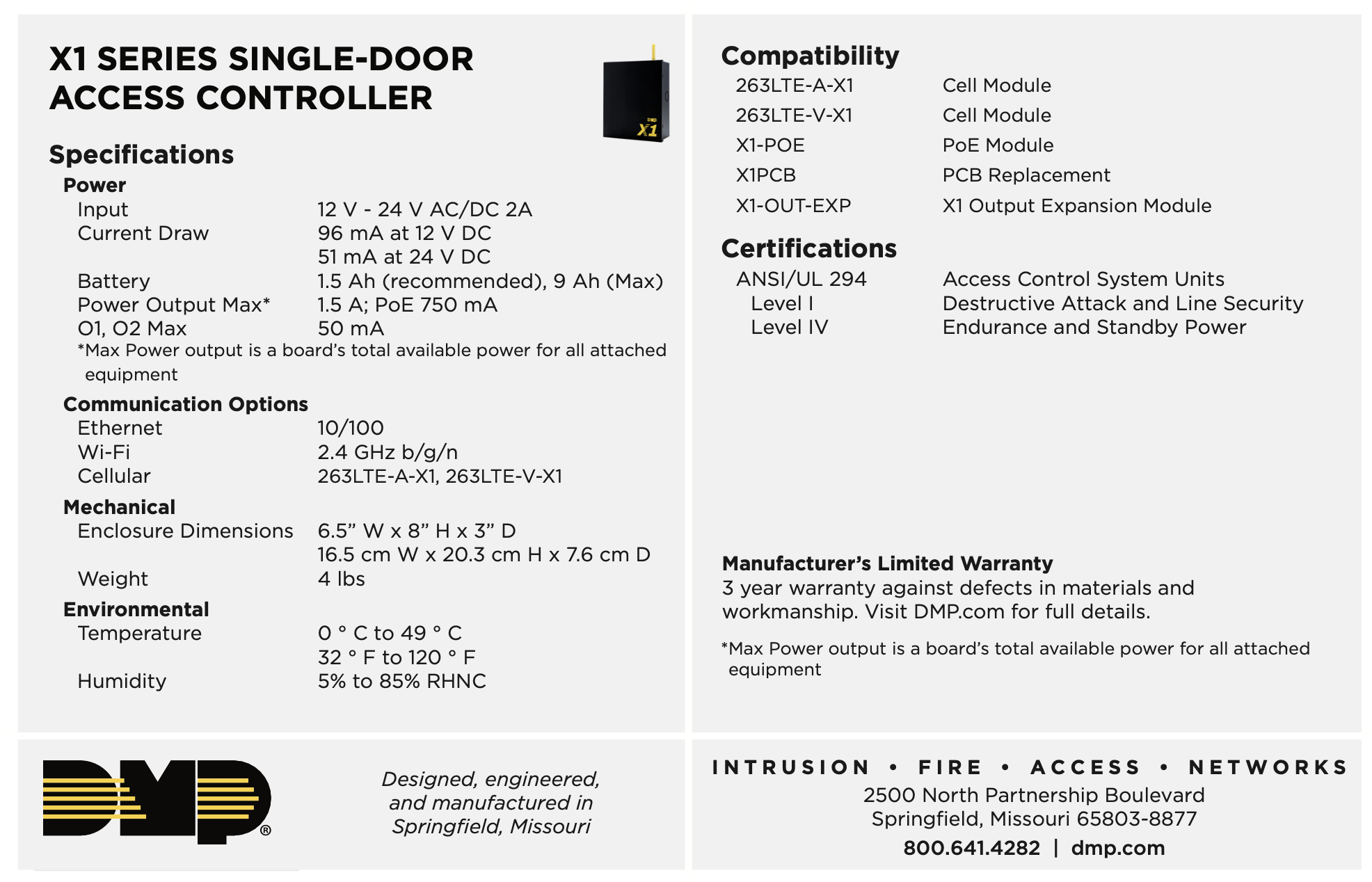
Cell Module Removal
- Unscrew the washer on top of the enclosure and remove the cell module antenna.
- Unplug the cell module from the cell header.
- Pinch the tab of the standoff to release the module from the door controller.
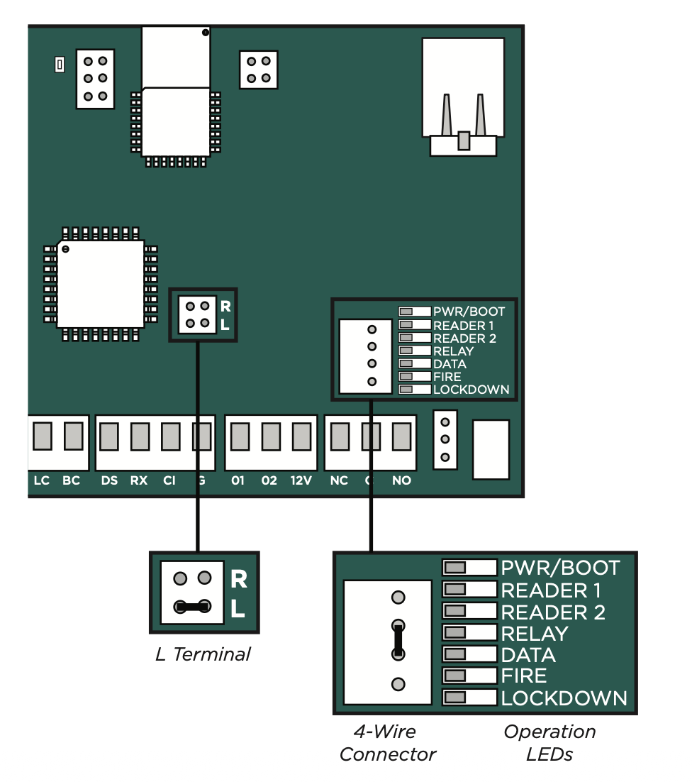
Door Controller Initialization
- Place a jumper over the L header of the door controller.
- Within 15 seconds, place a jumper on the center two pins of the 4-wire connector (short the green and yellow together). Reader 1, Reader 2, Fire, and Lockdown operation LEDs turn on.
- Within 15 seconds, remove both jumpers. The above LEDs will turn off. The Power LED will turn on steady to indicate the factory default is complete.