The ADEMCO 5819 Shock Processor Transmitter connects to inertia type shock detectors that are mounted externally to the transmitter case (detector not supplied), and is intended for use only with a wireless alarm system that supports 5800 Series wireless receivers.
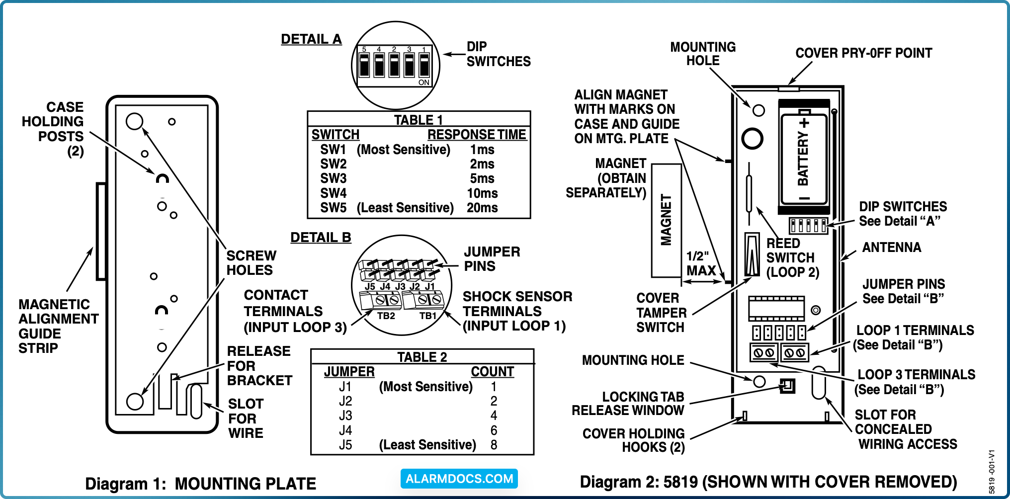
The 5819 has three unique zones. The first is for a wired, normally closed shock sensor loop (TB1), the second is for a closed contact loop using the unit’s built-in magnetic reed switch in conjunction with a magnet, and the third is for a wired closed circuit contact loop (TB2).
The 5819 has a built-in cover tamper switch that activates when the cover is removed.
Mounting
For proper orientation of the unit in relation to the mounting plate, loop wiring, DIP switch adjustment, jumper positions, and/or magnet, read all of this section before installing the unit.
The description that follows assumes that the unit will be mounted as shown in the diagrams, with the magnet (if used) located to the left of the unit. The unit can be installed in any direction, as long as the relationship of the unit to its mounting plate and (if used) magnet is maintained.
Although two mounting holes are provided in the unit that would permit mounting directly to a surface, it is recommended that the mounting plate be used as described in this document, for ease in removing the unit for servicing should it become necessary.
Before mounting the transmitter permanently, conduct Go/No Go tests (see control’s instructions) to verify adequate signal strength and reorient or relocate the transmitter if necessary.
1. Remove transmitter’s cover by inserting the flat blade of a small screwdriver into the pry-off slot nearest to the cover’s decorative ribs, and twisting the blade.
2. Disengage the supplied mounting plate from the unit by inserting the blade of a small screwdriver into the locking tab release window (see Diagram 2) and pressing it against the locking tab (see Diagram 1) while sliding the plate downward along the case back.
3. If a shock processor or wired contact loop is to be used with concealed wiring, feed the wires through the concealed wiring entry hole at one corner of the plate. For surface wiring entry, a thin “breakout” area is provided in the case wall.
4. Install the mounting plate, with its case-holding posts pointing up (in this example), in the location selected.
5. Attach the case back to the mounting plate by sliding the keyhole slots in the case back down onto the mounting plate’s case-holding posts. The locking tab will click as the case back locks in place.
6. If the unit’s REED SWITCH is to be used, mount a 5799 Magnet (obtained separately) adjacent to the alignment marks on the case and the mounting plate’s alignment strip (see Diagram 2).
7. Set response time (from Table 1) using the DIP switches. SW1 sets a response time of 1mS. SW5 sets a response time of 20mS. For a response time of 0.5mS, set all DIP switches to OFF (as shown in DETAIL A in Diagram 1 above).
8. Set the pulse count jumper (see Table 2). The pulse count is reset 3-seconds after the first pulse is detected. There is an LED on the PCB that flashes rapidly on transmission.
WIRING CONNECTIONS
With the battery still not inserted, connect the shock processor loop (if used) to the unit’s loop TB1 terminals (see Detail “B”). The contact loops must use closed circuit devices. TB2 can be used for normally closed contacts.
“ENROLLING” THE TRANSMITTER SERIAL NUMBER
Each 5819 Shock Processor has its own unique serial number permanently assigned during manufacture. Each input of the transmitter also has a distinct “loop” number that must be input to the control panel during installation. Assign each to an individual zone and designate the Input Type as “RF” (Supervised RF).
The serial number can be input by one of the following methods:
- “Enrolled” by transmitting from the device during zone programming (pressing the tamper switch, shorting any loop, etc.).
- Entered through the keypad at the “Input S/N” or “Transmit Now” prompt during manual zone programming.
- Entered through COMPASS Downloading Software and downloaded to the control.
When programming the 5819 transmitter’s serial number at the control panel, do the following:
- At the “Input Type” prompt, enter “3” for RF (Supervised RF).
- When prompted for the loop number, enter the input loop you are using (see Diagram 1). See the control panel’s installation instructions for specific programming procedures.