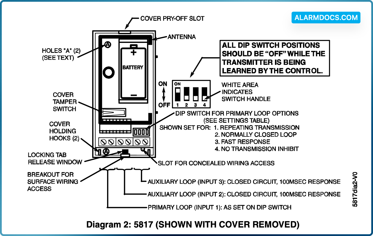
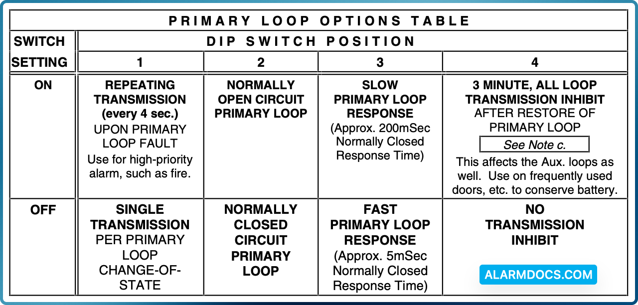
The 5817 Multi-Point Universal Transmitter may have three contact loops connected to it. Each loop transmits a unique ID code to a 5800 wireless system receiver connected to the system control panel. The Primary Loop has several DIP switch selectable options that determine its connection requirements, response, and transmission characteristics (see DIP switch setting table on next page). The two Auxiliary Loops are closed-circuit, with a nominal response time of 100mSec. For UL installations, no contact in any of the loops may be more than 3 feet from the transmitter.
A built-in cover tamper switch is activated when the cover is removed.
ENROLLING THE TRANSMITTER IDs
The 5817 has its own unique identification codes permanently assigned during manufacture. It is not necessary to program the transmitter IDs during installation. Instead, the control unit is required to “enroll” the transmitter IDs at some point prior to the transmitter’s usage in the alarm system.
The control unit’s installation manual contains general information on the “enrolling” procedure, but the information given herein pertains specifically to the 5817.
- Place a 3V battery in the battery holder, as described later in BATTERY
- Make sure that the DIP switch’s 4 positions (see Diagram 2) are all OFF.
- Set the system ready for enrolling the ID code of one of the 5817’s loops (inputs) to be used, as described in the control’s instructions. The 5817 should be treated as “RF” (i.e., supervised RF) Type (mandatory for UL installations).
- Proceed with enrolling the inputs of the loops to be used, as described in the control’s instructions.
Mounting
For proper orientation of the unit in relation to its wall mounting plate and the loop wiring, read all of this section before installing the unit.
The description that follows assumes that the unit will be mounted as shown in the diagrams. The unit may, however, be installed in any direction, as long as the relationship of the unit to its mounting plate is maintained.
Although two holes are provided in the unit that would permit mounting directly to a surface (holes “A” in Diagram 2), it is recommended that the mounting plate be used, as described below, for ease in removing the unit for servicing should it become necessary.
Before mounting the transmitter permanently, conduct Go/No Go tests (see control’s instructions) to verify adequate signal strength and reorient or relocate the transmitter if necessary. When a satisfactory location is found, remove the battery and proceed with installation.
1. Remove the transmitter’s cover by inserting the flat blade of a small screwdriver into the pry-off slot at the end of the unit farthest from the cover’s decorative ribs, and twisting the blade.
2. Disengage the supplied mounting plate from the unit by inserting the blade of a small screwdriver into the locking tab release window (see Diagram 2) and pressing it against the case locking tab (see Diagram 1) while sliding the plate downward along the case back.
3. If concealed wiring is to be used, feed the wires through the concealed wiring entry hole at one corner of the plate (surface wiring is mentioned in Step 5 below).
4. Install the mounting plate, with its case holding posts pointing up (in this example), in the location selected as described in the control unit’s installation instructions. Use the flat-head screws supplied.
5. If concealed wiring is to be used, feed it through the slot in the case back but do not connect to the terminal block yet. Surface wiring should enter via the thin “breakout” area provided in the case wall.
6. Attach the case back to the mounting plate by sliding the keyhole slots in the case back down onto the mounting plate’s hooks. The locking tab will click as the case back locks in place.
7. Set the DIP switch (after the control has enrolled the transmitter’s input IDs) for the desired primary loop characteristics, as described in the table below.
Notes
- a. While the transmitter is being enrolled by the control, all DIP switch positions should be OFF.
- b. Except in the case of the position 4 ON setting, the Auxiliary loops are not affected by the DIP switch settings.
- c. For UL installations with fire zones, the position 4 ON setting must not be used.
WIRING CONNECTIONS
With the battery still not inserted, connect the loop wiring to the unit’s terminals (see Diagram 2).