The 850 Series Fire Alarm Pull Station is a die-cast metal manual pull station available in single action (850S) or dual action (850D, Figure 1) models with SPST (single pole single throw) contacts and terminal strip connections. The normally open contact, which closes when the pull station is activated, is rated for 1 Amp @ 30 VDC. The contacts are gold-plated to avoid the risk of corrosion. The 850 Series has been tested by UL and found in compliance with the pull force requirements of the Americans with Disabilities Act (ADA).
COMPATIBILITY
All DMP control panels
MOUNT THE PULL STATION
The pull station may be surface-mounted with a DMP Model 850-SB Surface Backbox or a DMP Model 850-WP Weatherproof Backbox or flush-mounted on a standard single-gang switch box. When mounting the pull station, follow all local codes and regulations. To comply with ADA standards, the pull station must be mounted less than 48” above the floor for front wheelchair access and less than 54” above the floor for side wheelchair access.
Surface Mounting
The surface-mount installation uses a red die-cast or sheet metal backbox with 4 pre-drilled 0.187” diameter mounting holes. A #8 screw or smaller can be used to attach the backbox to a wall. After mounting, attach the conduit to the backbox. The cast backbox has an opening for the conduit that is tapped for a 1/2” NPT fitting that may be oriented at the top or bottom of the box when attached to the wall. The sheet metal backbox has knockouts for attaching conduit.
Flush Mounting
Flush-mount installations may be attached to a standard single-gang switch box (not supplied by DMP). The only difference between a surface-mount installation and a flush-mount installation is two #6-32 screws that are placed through the slots that are centered on the metal mounting plate.
INSTALL THE BREAKROD
- Unlock the housing by turning the key clockwise and swing down the front to expose the sheet metal mounting plate.
- Mount the metal plate to the backbox using the four #8-32 x 1/4” supplied screws.
- Move the PULL handle to a 450 angle to the housing face. Insert a breakrod into the cavity below the PULL handle.
- Place the PULL handle back to the normal position (flush to the housing).
- Hold the PULL handle in place, move the housing to the upright position, and lock.
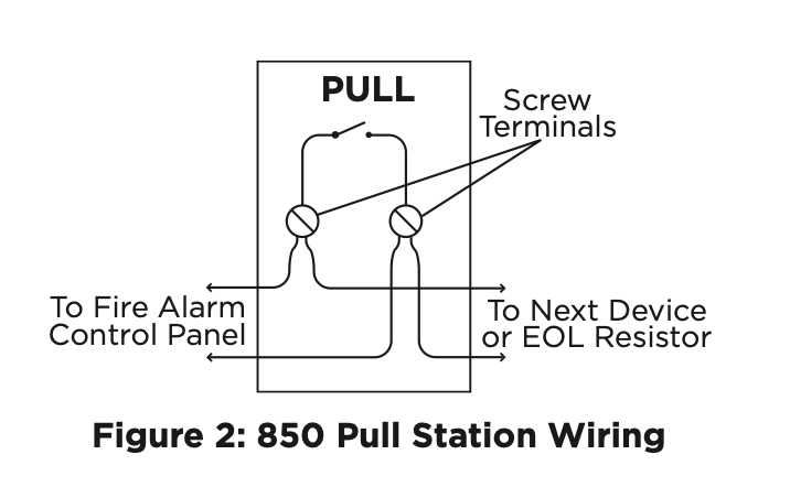
WIRE THE PULL STATION
Connect wiring to the terminal block as shown in Figure 2. The wire should be placed under the clamping plate—not wrapped around the terminal.
SPECIFICATIONS
- Switch Rating: 1 Amp @ 30 VDC
- Pull Station Dimension: 4.75” H x 3.25” W x 1.1” D (12.07 cm H x 8.23 cm W x 2.79 cm D)
- Mounting Box Dimension: 4.75” H x 3.25” W x 2.25” D (12.07 cm H x 8.23 cm W x 5.72 cm D)
- Color: Red with raised white letters, with a white pull handle with raised red letters
CERTIFICATIONS
ANSI/UL 38 Manual Signaling Boxes for Fire Alarm Systems