Alarm Docs
  • Submit Article
  • Contact Us
  • About Us
  1. Home
  2. Fire Alarm
  3. NFS-640: Circuit Board Components
Searching...

Other Articles

  • IQ INSTALLER
  • DMP: 860 relay module
  • 711: Zone Expansion Module
  • GEMC-EZM8 – Installation Instructions
  • PG-WLSHW: Wiring a fire zone
  • EVD-2 wiring with 2 additional EVD-R
  • Vista: How to enable Contact ID
  • DMP: How to program static IP
  • ADC: Internet connection type compatibility
  • StarLink SLE-LTE: Wiring diagram
  • StarLink SLE-LTE: Terminal Descriptions
  • PowerSeries Neo: Change entry delay
  • Vista: How to program house code
  • How to address 6160 keypad on Vista 21
  • 1100DH: Installation Guide
  • OPTEX Beams: Master/slave selector switch setting
  • Lynx: Summary of connections
  • PROTAKEOVER: Setup guide
  • PGP922: Installation Guide
  • Qolsys IQ4: How to disable the panel camera
  • Qolsys IQ4: How to disable the panel tamper
  • Qolsys IQ4: How to enable wellness page
  • Qolsys IQ4: Wellness page
  • PGPx303: Installation guide
  • XF6: Terminals 17-28

NFS-640: Circuit Board Components

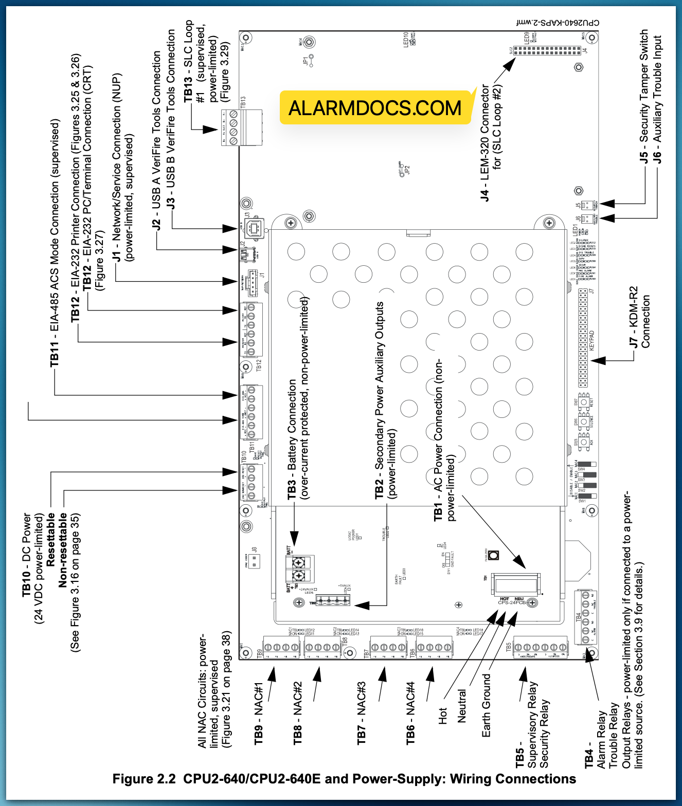
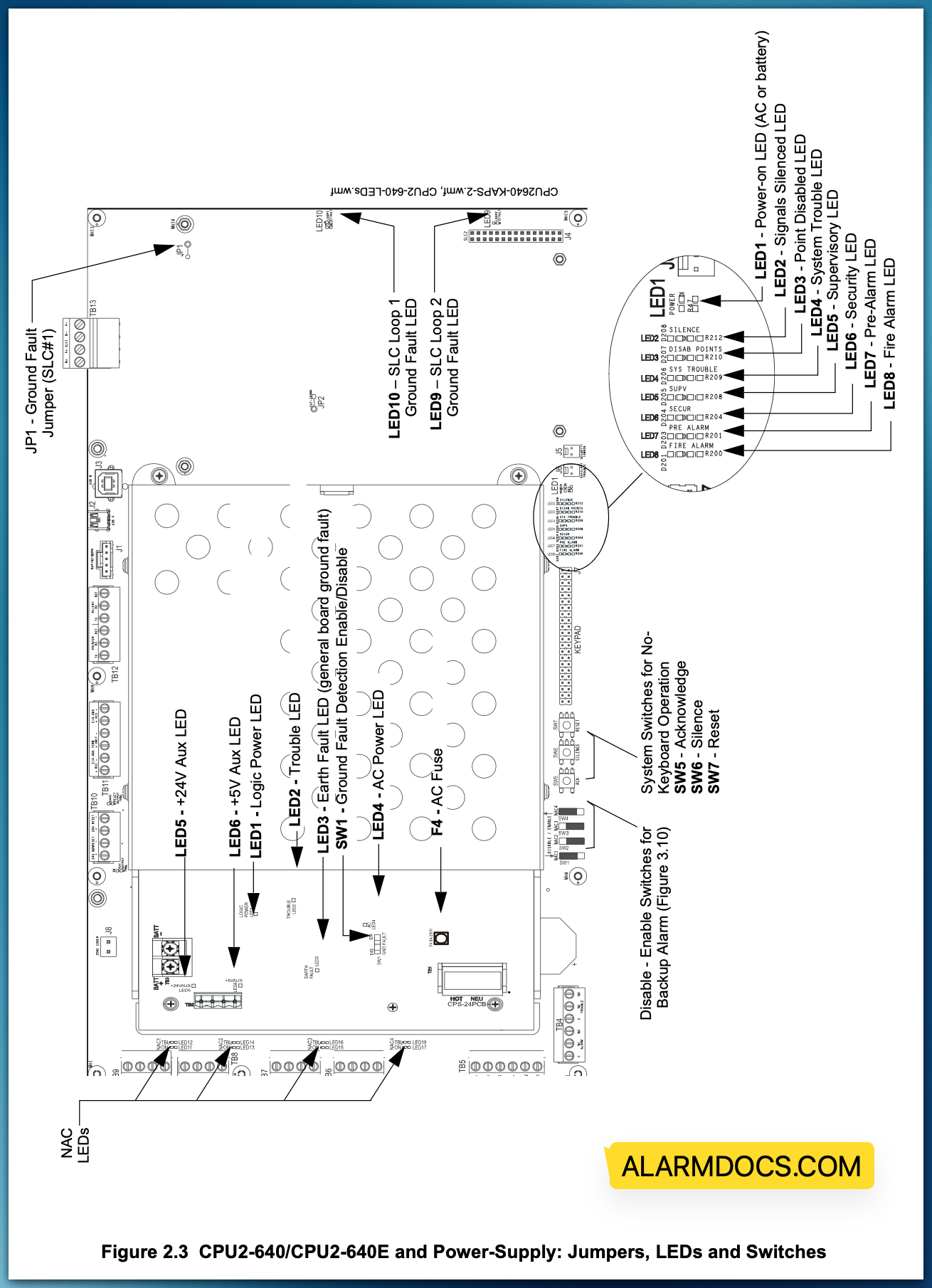
The following two figures illustrate the location of the various connections, switches, jumpers and LEDs on the CPU2-640/CPU2-640E and its power supply. Figure 2.2 shows wiring connections; Figure 2.3 shows jumpers, LEDs and switches. See Section 3 “Installation” for larger images and more details. (Larger images are referenced on these drawings.)

Tagged: nfs640
Was this article helpful?
Yes No
© Copyright 2026 - AlarmDocs.Com