The 5869 Holdup Switch/Transmitter is a finger-operated RF transmitting device used for activating a holdup signal at the security system control, and/or any other security application. The 5869 is typically mounted under a counter or money draw for inconspicuous operation. When the transmitter is activated, it sends an RF signal to the control panel, which then sends a burglary alarm to the central station
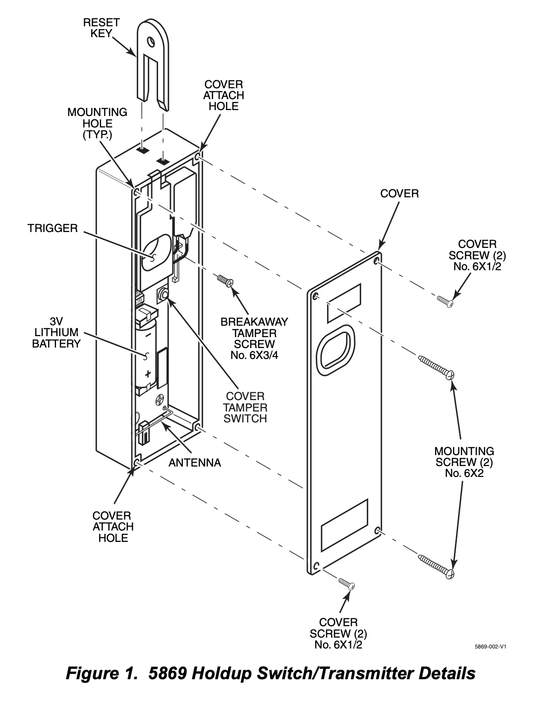
Once the 5869 trigger (Figure 1) is activated, the supplied reset key K4563 must be used to reset the device. The 5869 also contain tamper switches that are activated either when the cover is removed, or when the unit is forcibly removed from its installation location.
The 5869 has a permanent serial number assigned during manufacture used for enrolling the 5869 with the security system control panel. To enroll the 5869, refer to the respective Security System Control Panel Installation and Setup Guide.
MOUNTING
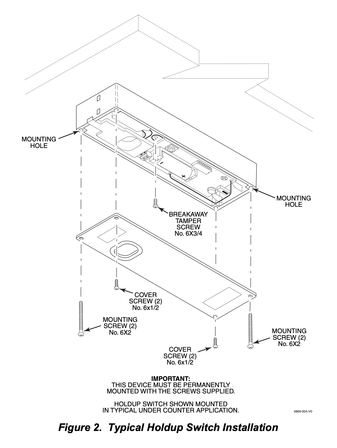
Mount the 5869 under a counter or money drawer for easy access by the cashier. Refer to the figure and steps that follow for typical mounting installation.
Before mounting the 5869 permanently, perform Go/No Go tests to verify adequate transmitter signal strength at desired mounting location (refer to the Security System Control Panel Installation and Setup Guide).
1. Install the battery into the battery holder observing correct polarity as shown in Figure 1.
2. Position the case to the desired location and install one No. 6 x ¾ screw (supplied) at the breakaway tamper release hole as shown in Figure 2 .
3. Secure the cover to the case with the two screws (No 6 x 1/2) as shown in Figure 2.
4. Secure the case with the cover to its mounting location.
PROGRAMMING
The 5869 Holdup Switch/Transmitter should be programmed as a 24-hour silent zone type.
The 5869 is one closed input loop zone (loop 1).
Vista programming
- Enter programming mode and zone programming
- Press *56 to enter zone programming.
- Respond “Yes” to the “Set to Confirm” prompt.
- When prompted for the zone number, enter the number of an available zone.
- The panel will now prompt for the “Zone Type”.
- Select the 24-hour silent or 24-hour police panic option to ensure the alarm is triggered without the keypad sounding an immediate local alarm.
- You may also need to set the “Partition” to the correct partition number.
- At the “Input Type” prompt, select 03 for RF.
- At the “Input S/N” prompt, activate the 5869 three times to have the panel auto-learn its serial number.
- Press the panic button (pull the finger slot) and then reset it with the key.
- Repeat this process two more times within about 52 seconds.
- The panel should beep to confirm the serial number has been learned.
- Save the zone by exiting the programming menu.
BATTERY INSTALLATION/REPLACEMENT
1. Remove the screws securing the 5869 cover and case to its mounting location.
2. Remove faulty battery and dispose of properly.
3. Observing correct polarity, insert the battery into the battery holder.
4. Re-install screws to secure cover and case.