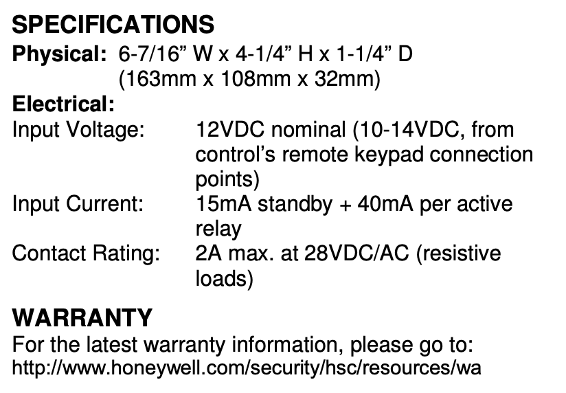
The ADEMCO 4204 Relay Module provides from one to four dry, form-C (SPDT) relay outputs to compatible control/communicators. It connects to the control’s keypad wiring terminals.
The 4204 can be mounted inside the control’s cabinet or mounted remotely depending on the application. Refer to the UL notes below for certain restrictions.
If mounted remotely, the 4204 has a built-in tamper switch that allows it to detect and report the removal of its cover to the control. Second, communication to the 4204 is supervised so that it cannot be disconnected from the keypad wiring without detection by the control. If the wiring is cut, a tamper or alarm signal will result, to indicate that this device (and possibly other devices connected to the keypad wiring) has become inoperative.
For UL Installations:
When used with controls that do not support cover tamper or supervise communications wiring to the 4204, mount the 4204 inside the control’s cabinet.
When used with controls that support cover tamper and supervise communications wiring to the 4204, mount the 4204 may either be mounted inside the control’s cabinet or mounted remotely.
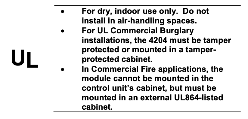
When mounted inside the control’s cabinet, some controls allow the 4204 to be mounted horizontally as follows: insert the self-tapping screws (provided) in two adjacent raised tabs on the back of the cabinet. Leave the heads projecting 1/8”. Hang the 4204 on the screw heads via two of the slotted holes on the back of its housing. The 4204’s cover need not, in this case, be tamper-protected. Set DIP switch 1 to “ON” if the cover is not used (see table). See the control’s instructions for additional information.
When the 4204 is mounted remotely, it can be mounted horizontally or vertically and the built-in tamper switch can be used. Wires can exit from the side or via the breakout on the back of its housing. The DIP switch must be set with its position 1 “OFF” and when the installation is completed, the unit’s tamper-protected cover must be replaced.
Affix the connections label that accompanies the 4204 to the inside of the 4204’s cover (if the cover is used) or to the inside of the control’s cover.
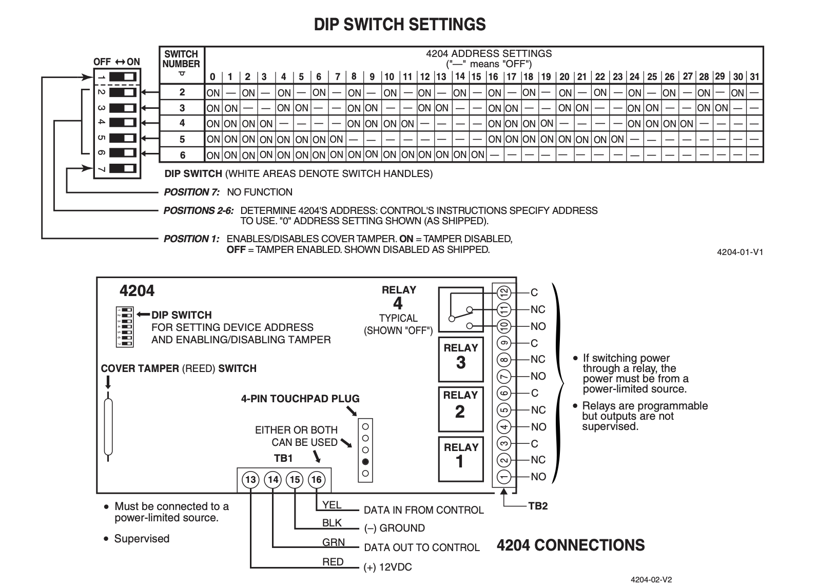
Select and set an address for the 4204, using its DIP switch as shown in the DIP switch table. Each 4204 must be assigned a unique address so the control can identify and communicate with the 4204. The address to set is determined by the particular control to be used. See the control’s installation instructions. As shipped, the DIP switch is set for address “0”.
Make connections to the 4204’s four relays via 12- position terminal block TB2. Refer to the control’s installation instructions for specific information on how to program the activation options for the relays.
Make connections to the control’s keypad wiring points via 4-position terminal block TB1, the 4-pin plug, or both (wire color connections are the same). See the diagram on the other side of this page.
Program a 4204 relay module
- Enter programming mode. Enter the installer code followed by 800
- The screen should display “Enter Output No.”
- Enter
1to set the output type to relay. - Enter the address you set on the DIP switches.
- Enter the relay number on the 4204 module (1 through 4).
Program the output function
- At the
*80prompt, enter the output function number to define how the relay will be triggered - Set the “Activated By” prompt. You can choose:
1for a zone list.2for a zone number (enter the zone number).3for a zone type (enter the two-digit zone type).
Choose the action for the relay, such as 2 for “Stay Closed” or 1 for “Closed for 2 seconds”.
If you programmed it to “Stay Closed,” you may need to program a second output function to return it to its original state when the trigger is cleared.
Exit programming
At the end of the programming sequence, press *99 to exit and save your changes.