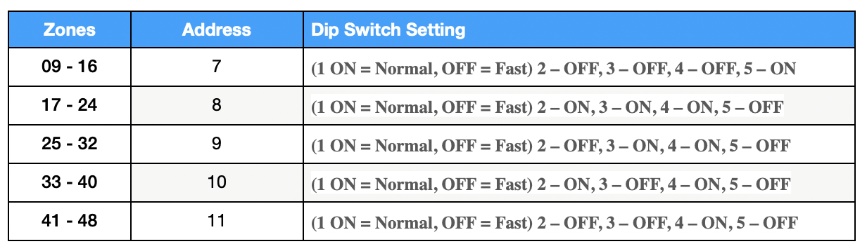
To program a 4219, you must first set its address using the DIP switches on the module itself, then connect it to the control panel’s ECP bus, and finally, enter the panel’s installer programming to assign the zones. The specific DIP switch settings and panel programming steps will vary based on your control panel model and the desired zone numbers, so always consult the module’s and panel’s instruction manuals.
Wire the module to the control panel
- Connect to ECP bus: Wire the 4-terminal block (TB2) on the 4219 to the ECP terminals on your Vista control panel’s keypad bus.
- Connect zone wires: Connect the hardwired sensors to the 12-position terminal block (TB1) on the 4219.
- Install resistors: If using end-of-line resistors (EOLR), connect a 2K-ohm resistor across the end of each zone loop.
Program the zones on the control panel
- Enter installer programming: From the keypad, enter [Installer Code] + 8 + 00. The default installer code is 4112.
- Go to zone programming: Press *56.
- Program each zone: Follow the prompts to select each zone you want to program. The first zone on the 4219 will correspond to its assigned address (e.g., zone 9 for address 7).
- Set zone type: For zones connected to the 4219, set the zone type to “Aux Wire” or equivalent, not RF transmitter.
- Exit zone programming: 00
- Exit programming. Press *99