The CellCom Series Universal Alarm Communicator provides a fully supervised alarm communication path for any burglary, commercial fire, or residential fire control panel. The CellCom Series can be connected to any control panel’s dialer output and used to capture Contact ID messages based on SIA DC-05-1999.09-DCS. The communicator also provides four input zones and two open-collector outputs for connection to burglary, commercial fire, or residential fire control panel outputs and zones. Zone 4 allows a connection to the bell output of an existing control panel.
The communicator operates in a variety of applications: Dialer Connection, Zones 1-4 Input Connections, or Zone 4 Bell Connection.
The CellComF Series Fire Alarm Communicator includes a red enclosure and a Model 685-R (Red) Backbox.
Power Connection Terminals
The communicator may be powered from the 12 VDC or 24 VDC auxiliary output of the control panel. Observe polarity and use 18-22 AWG wire to connect the communicator terminal +12 to the +12 or +24 V positive terminal on the control panel auxiliary output. See Figure 1. Connect the communicator terminal G (ground) to the negative terminal on the control panel auxiliary output.
Control Panel Standby Power
During a power outage, the communicator draws power from the control panel’s backup battery. The communicator must be included in the standby battery calculations for the control panel.
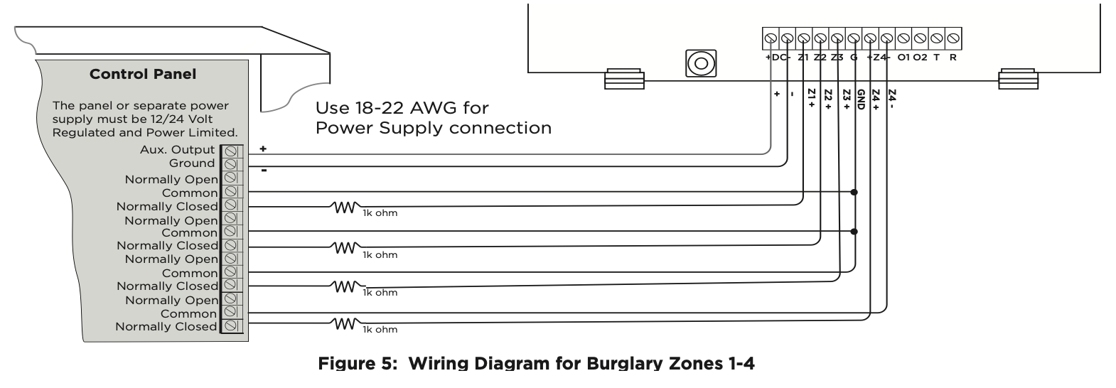
Zones 1‑4
Terminals Z1 to Z3, G (ground), Z4+ and Z4- provide four zones to connect to individual relay outputs on the control panel. Zone 4 (Z4+ and Z4-) can be connected to the control panel bell output. See Zone 4 Bell Connection.
Open‑Collector Outputs
Terminals O1 and O2 can be programmed to indicate the activity of the zones or conditions occurring on the system. Open-Collector outputs do not provide a voltage but instead switch-to-ground the voltage from another source. Maximum voltage is 30 VDC at 50 mA. The outputs can respond to any of the conditions listed below:
- Activation by zone condition: Steady, Pulse, Momentary, or Follow
- Communication
- Armed area annunciation
- Remote Arming Output
Dialer Connection
Directly connect the Telco phone line (tip and ring) from the control panel to the terminal R (Ring) and one into terminal T (Tip). For more information, refer to “CID, SIA, and 4-2 Dialer Connection”.
Programming (PROG) Connection
A 4-pin programming header is provided to connect a keypad when using a DMP Model 330 programming cable. This provides a quick and easy connection for programming the communicator. For 24 VDC applications using the communicator, connect the keypad using a Model 330-24 4-wire programming harness with an in-line resistor. After programming is complete, remove the keypad.
Tamper
The tamper is pressed when the cover of the communicator is secured onto the enclosure. When the cover is removed, the communicator sends a tamper trouble message to the central station.
Reset Button
The reset button is located on the upper right side of the circuit board and is used to reset the communicator. After resetting the communicator, begin programming within 30 minutes. If you wait longer than 30 minutes, reset the communicator again.
Load Button
Firmware can be updated with the programming header. Firmware updates are available for download, free of charge, on the DMP Dealer Direct website at DMP.com/Dealer_Direct.
Performing a Firmware Update
To update the communicator with a new firmware version, complete the following steps at the protected premise:
399 Programming Cable
- Connect a DMP 399 Cable from the programming header to the serial port of your PC operating Remote Link and containing the communicator RU file.
- Start Remote Link and create or open the account that matches the communicator to be updated.
- Set the connection information type to direct with a baud rate of 38400 and choose the appropriate COM port.
- Select Panel > Remote Update, then select the correct RU file for the communicator.
- Press and hold the load button, then press and release the reset button.
- Release the load button and select <Update> in Remote Link.
- After the firmware update is completed, remove the 399 cable and press the reset button to resume normal operation.
Model 401 USB Flash Module
When loading the firmware RU file onto a USB drive, place the file in the root directory of the USB drive. The update cannot be inside a folder. Format the USB drive as FAT32.
Place only one firmware file in the root directory. If more than one RU file exists on the USB drive, the communicator will choose the RU file with the most recent date modified.
- Connect the USB flash drive to the Model 401.
- Press and hold the reset button on the communicator. You will continue to hold reset until step 6.
- Connect the assembly to the communicator’s programming header.
- Press and release the button on the Model 401.
- With your finger still on RESET, press and hold the load button. Continue to hold LOAD until step 8.
- Release the reset button.
- Press and release the button on the Model 401.
- When the green LED on the Model 401 starts a slow flash, release the load button. The slow flash will last 5 minutes, then the green LED will become steady, indicating the firmware version is updated.
- Press and hold RESET. Remove the Model 401, then release RESET to resume normal operation. In the event the Model 401 USB Flash Module is inadvertently removed from the communicator before the update finishes, repeat steps 1-9.
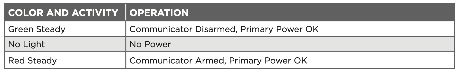
Backlit Logo
The backlit logo indicates the power and armed status of the communicator. Depending on the operation, the LED displays in red or green as listed in the Table 1. The LED indicates the armed state and status of the system primary power.
ECP and DSC Passthru
Perform an ECP or DSC Passthru and communicate through the communicator over the host panel’s bus. This also allows users to manage host panels through Virtual Keypad including arming, disarming, viewing zone status, bypassing zones, view history, manage users, and more.
Select a Location
Install the communicator away from metal objects. Do not mount the communicator inside or on a control panel metal enclosure. Mounting the communicator on or near metal surfaces impairs cellular performance.
Mount the Communicator
The communicator should be mounted to a wall using the included #6 screws in the mounting holes. See Figure 1. Mount the communicator in a secure, dry place to protect the communicator from damage due to tampering or the elements. It is not necessary to remove the PCB when installing the communicator.
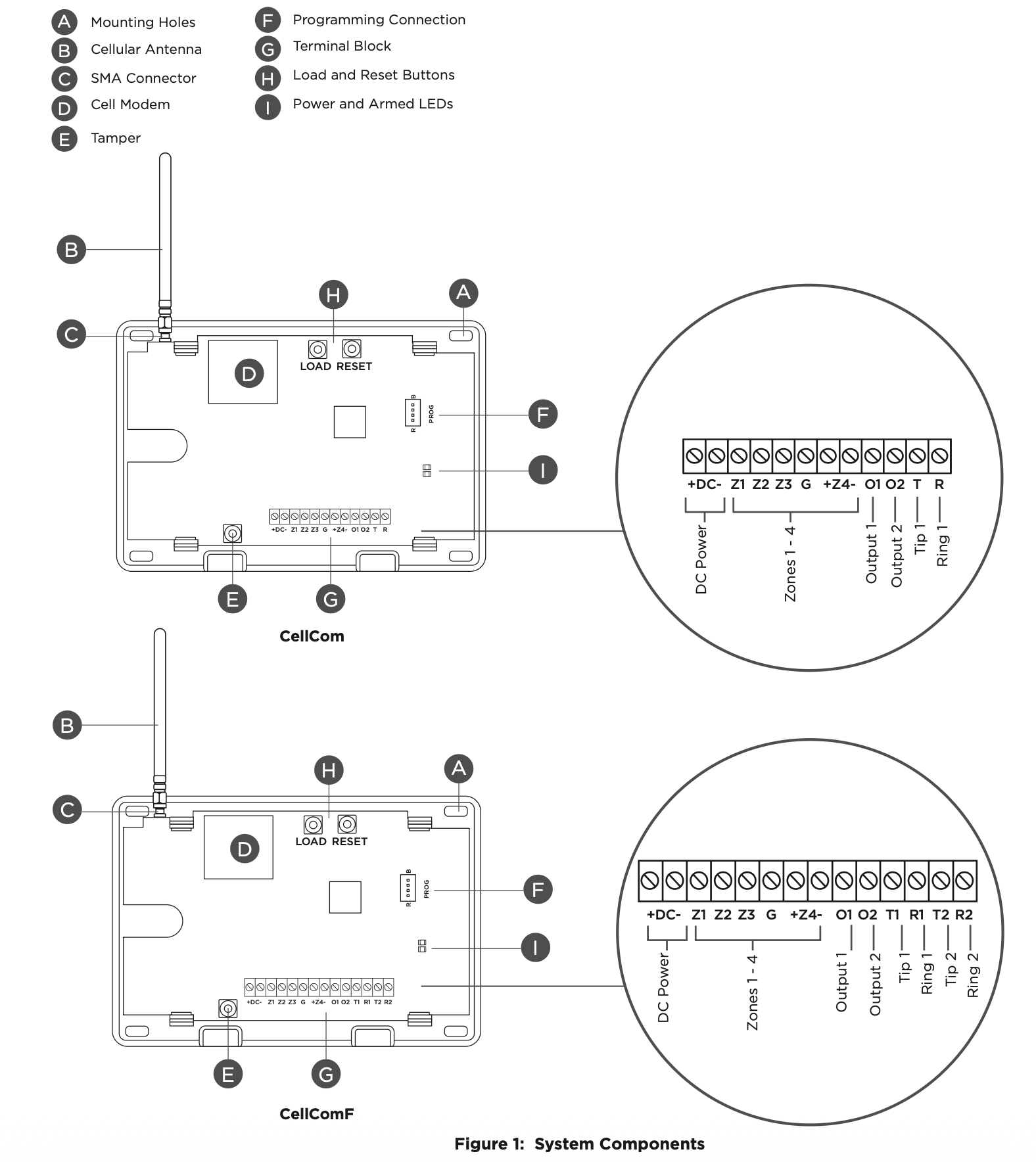
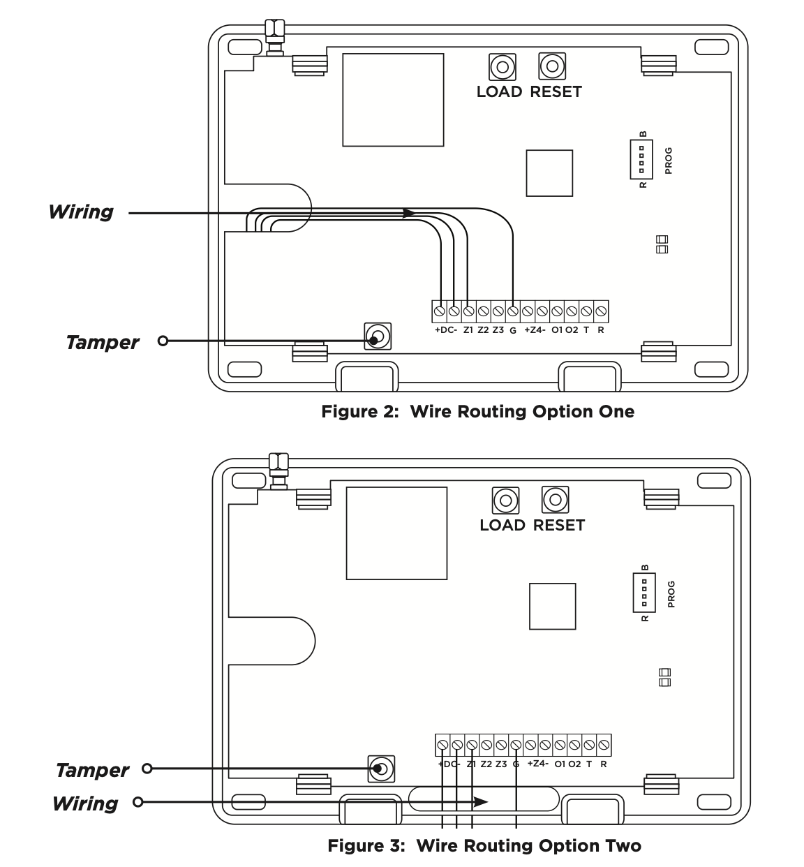
Wire the Communicator
When connecting component wires, route all wires so they will not interfere with the tamper switch. See Figure 2 and Figure 3 for wire routing options.
Connect the Antenna
Place the antenna onto the SMA connector. Refer back to Figure 1. Twist the antenna until it is securely tightened.
Replace the housing cover on the mounted base. Be sure to not damage any PCB components when removing or replacing the housing cover.
CID and 4-2 Dialer Connection
Directly connect one or both tip and ring terminals from the control panel to the communicator. See Figure 4. This connection captures Contact ID messages from any fire panel that are based on the SIA communication standard DC‑05-1999.09-DCS. Messages are then formatted into a Serial 3 message and sent to an SCS-1R Receiver or SCS‑VR Receiver.
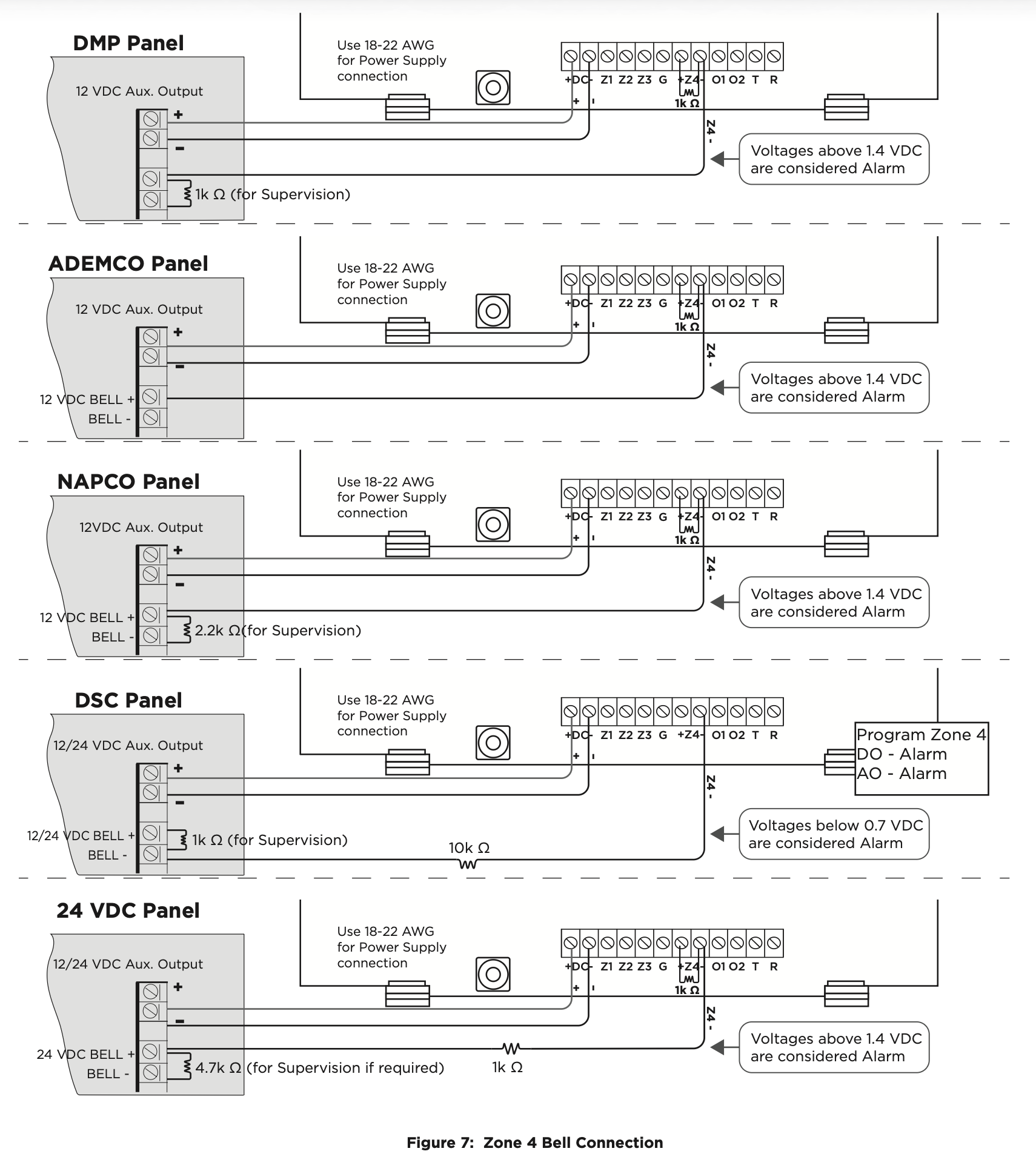
Zone 4 Bell Connection
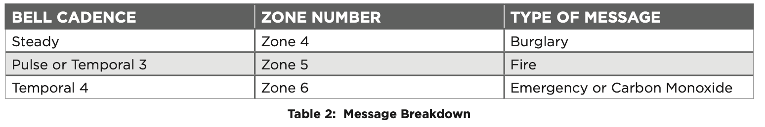
Zone 4 (Z4+ and Z4-) can be connected to the control panel bell output. This zone detects an alarm condition on the control panel by monitoring the voltage and cadence timing of the bell output. The communicator evaluates the first 3.5 seconds of bell cadence timing to detect the type of alarm sent. See Figure 6.
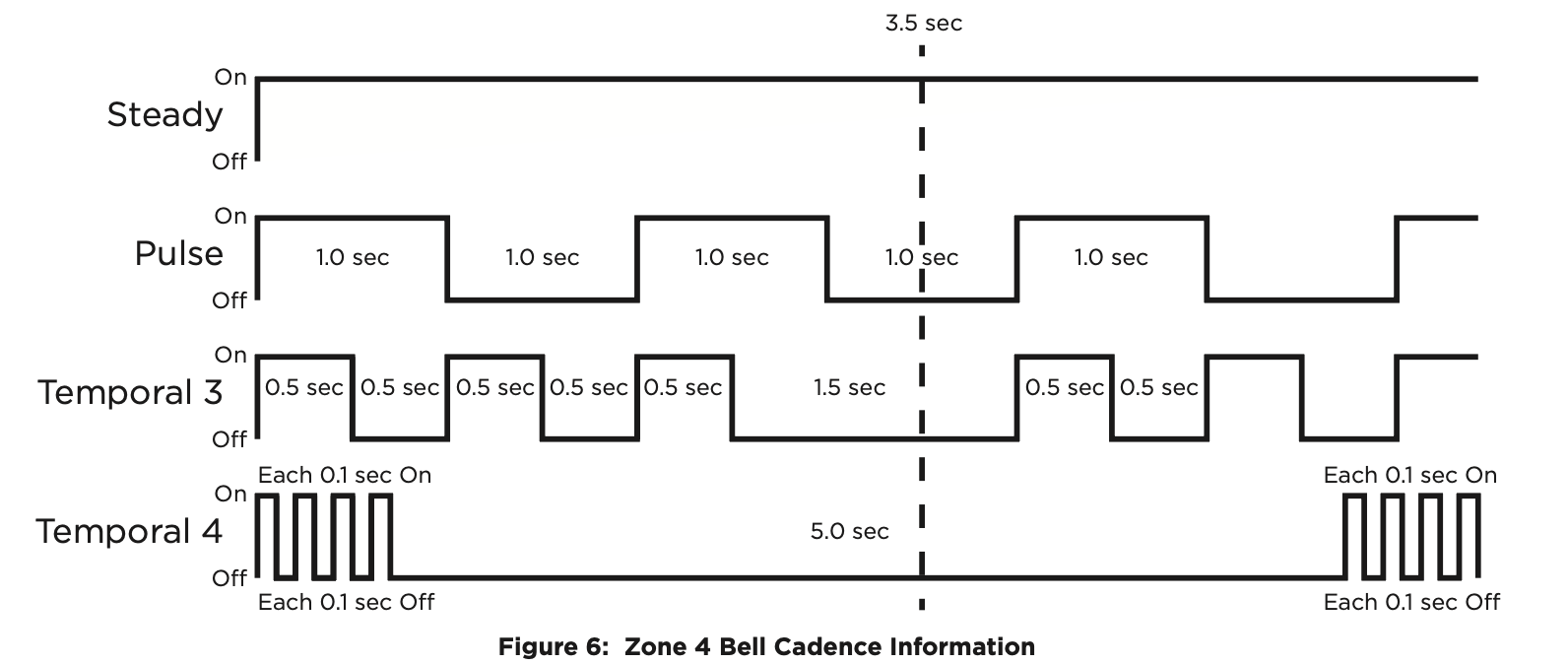
To enable alarm detection operation, Zone 4 Bell Connection must be programmed as Zone Type (A2) in Zone Information programming. See Table 2 for bell cadence type, zone number, and type of message sent to the receiver.
The communicator generates zones 5 and 6 using the zone name of zone 4 to send to the central station. Zones 5 and 6 cannot be preprogrammed in Zone Information. Dialer Connection cannot be used when using Zone 4 Bell Connection.
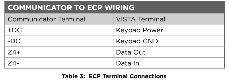
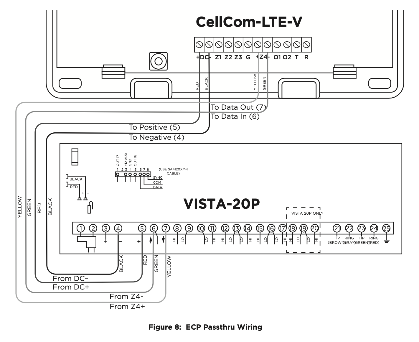
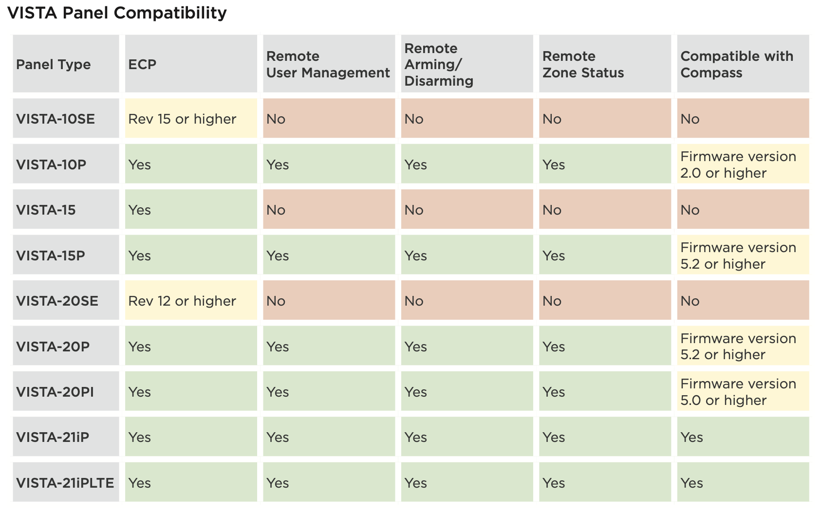
ECP Passthru Connection
The communicator can be connected to the ECP Bus of a compatible VISTA panel. Refer to “VISTA Panel Compatibility” for VISTA compatibility details. See Table 3 and Figure 8 for wiring details.
Configuration
To configure the communicator for ECP Passthru, set KEYPAD INPUT to ECP, program VISTA keypad device address 20, then use the ECP SETUP feature in the Diagnostics (DIAG) menu. For details, refer to “Keypad Input” and “ECP Setup”.
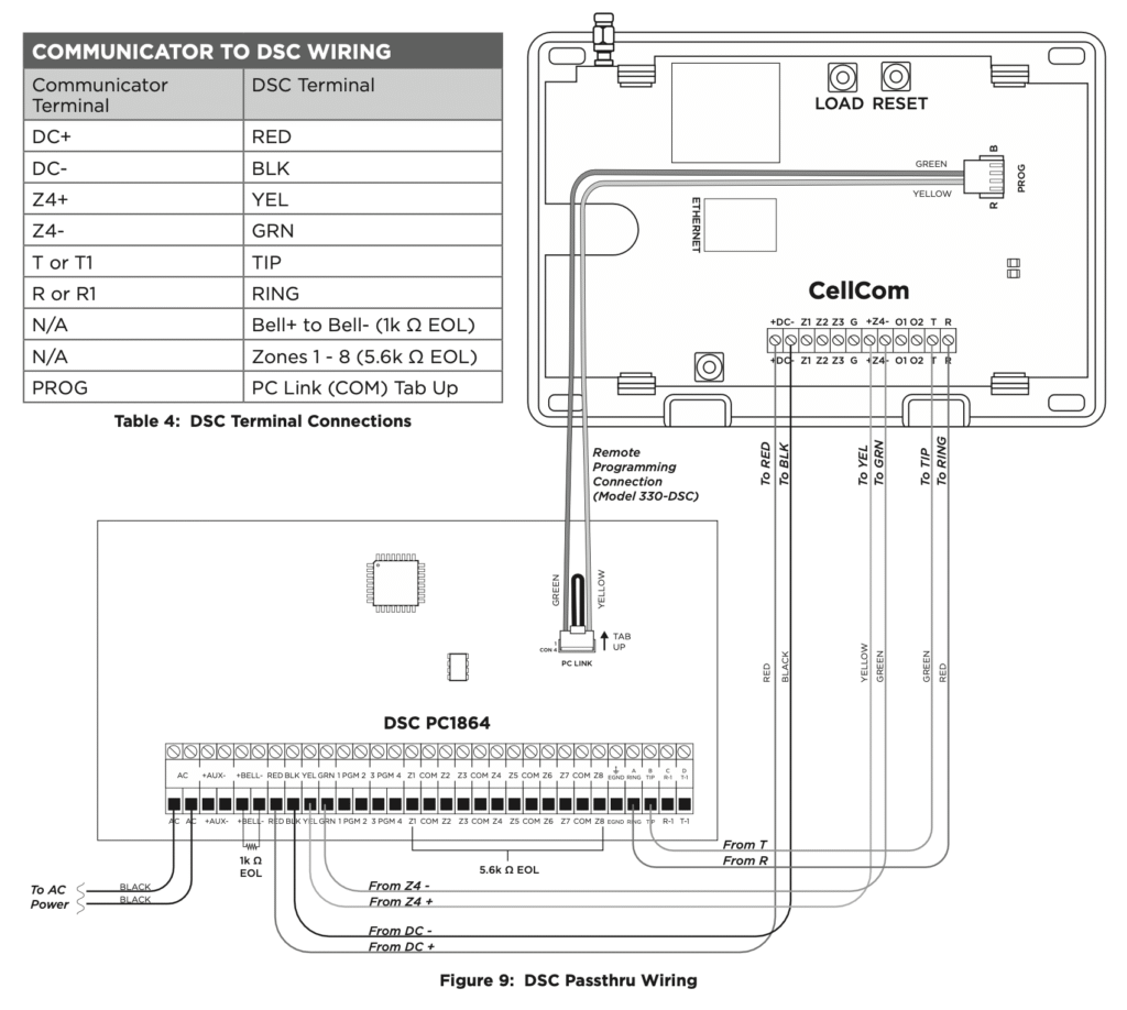
DSC Passthru Connection
The communicator can be connected to the DSC Bus of a DSC PowerSeries Model PC1616, PC1832, or PC1864. Refer to Table 4 and Figure 9 for wiring details.
Configuration
To configure the communicator for DSC Passthru, set KEYPAD INPUT to DSC in System Options and then use the DSC SETUP feature in the Diagnostics (DIAG) menu. For details, refer to “Keypad Input” and “DSC Setup”.
ADDITIONAL APPLICATIONS
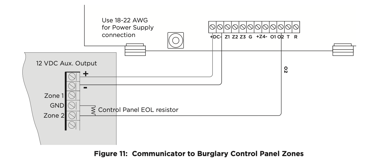
Use Outputs
A burglary control panel zone may be programmed as an arming zone and connected to output O1 or O2. See Figure 11. Program the output number in armed output or remote arming output in output options when programming the communicator. See Armed Output or Remote Arming Output. The communicator output connections can be used with any of the applications listed in this guide. See Applications.
Communicator to Panel Burglary Zones
- Connect the communicator’s Z1 (zone 1) terminal to the control panel’s armed output terminal.
- Connect the communicator’s O1 (output 1) terminal to the control panel’s keyswitch or arming zone.
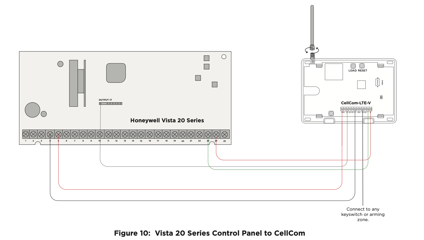
Honeywell Vista 20 Panel Wiring
- Connect the communicator’s Z1 (zone 1) terminal to output 17 on the control panel.
- Connect the communicator’s O1 (output 1) terminal to the control panel’s keyswitch or arming zone.
- Connect the T (tip) terminal on the communicator to terminal 23 on the control panel.
- Connect the R (ring) terminal on the communicator to terminal 24 on the control panel.
- Power the communicator by connecting its terminal +12V to terminal 5 on the control panel.
- Connect the communicator’s GND (ground) terminal to terminal 4 on the control panel.
To learn how to activate the Cellcom Activate module, search for “Cellcom Activate.”