General Information and Component Identification
The Honeywell 5816OD Wireless Outdoor Sensor (referred to as the Sensor) brings the convenience of wireless technology to the outdoors.
- Weatherized security protection for an outdoor environment. Great for sheds, barns, garages, pool gates, fences, and rural mailbox (notifications). Can be painted.
- Cover and rear tamper detection.
- Operating Environment: – 40 to +66°C (- 40 to +150ºF) at RH of 100% (UL: Rated at RH of 85%).
- Meets NEMA4X water protection.
- Sensor: 4-3/8″ × 2-1/16″ x 1-9/16″ Magnet: 4-1/16″ × 15/16″ × 1-7/32″ with spacer.
- Maximum Magnet Gap: Wood 1.75 in., Steel: 1.25 in.
- For extra wide gaps use the 7945-2GY external contact. (Always check installation to ensure there are no false alarms due to gap spacing.)
- For extended wireless range use the 5800RP (Repeater).
- UL: Approved for UL Commercial Burglary listed control panels (e.g., VISTA-50P) and receivers (e.g., 5881ENHC).
The 5816OD has two unique zones; the Loop #1 is for a wired closed circuit contact loop and Loop #2 is for the built-in reed switch (used in conjunction with a magnet). Either or both zones may be used.
A built-in tamper switch is activated when the cover is removed, or if the Sensor is detached from its mounting.
Installing / Replacing the Batteries
- Always change both batteries. Do not mix weak batteries with new batteries.
- Use two (2) lithium 1.5VDC AA cells. (For best life, use ‘veready’s Energizer Ultimate LITHIUM AA batteries, Honeywell part number 462) Alkaline batteries may be used but the battery life and temperature range will be reduced.
- OBSERVE BATTERY POLARITY.
Battery Replacement:
- Remove cover screw and swing Sensor to remove from Sensor Mounting Plate.
- Use screwdriver in any pivot point and pry Sealing Cover off. Replace batteries.
- Orient the Sealing Cover so the screw hole lines up with the screw hole in the sensor cover, and press to close.
- Engage Sensor tabs into mating holes in Sensor Mounting Plate and swing closed. Secure with cover screw.
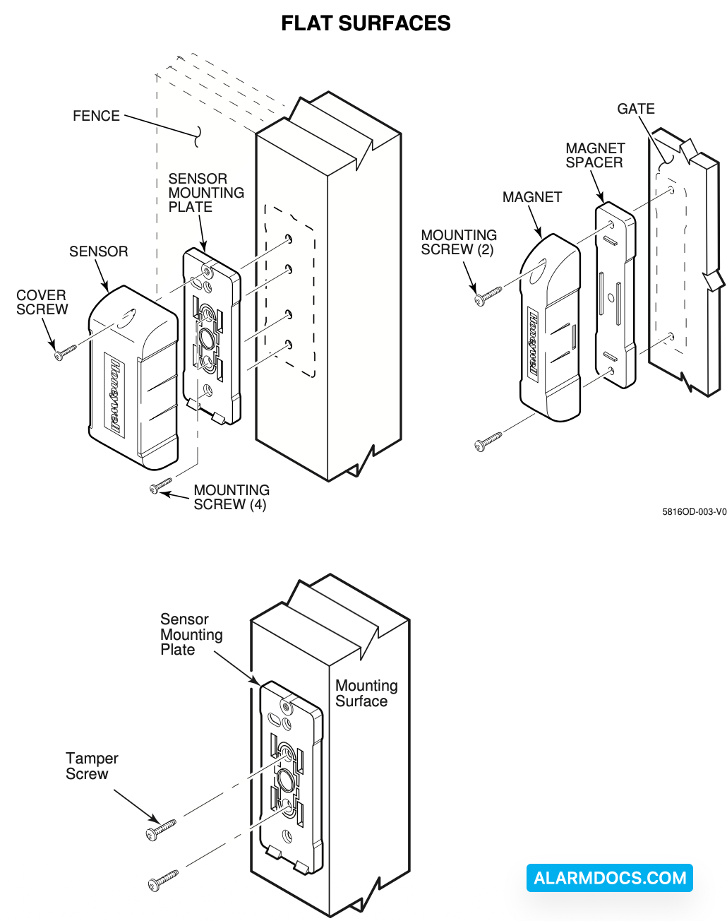
Mounting Guidelines
- Before mounting the Sensor permanently, conduct a Go/No Go test (see control panel’s instructions) to verify adequate signal strength. Reorient, relocate, or use a repeater if necessary.
- This device is intended for vertical surfaces (to be mounted at a sufficient height) where snow, ice and water buildup will not interfere with its operation.
- Before final mounting, ensure water protection by ALWAYS adding silicone caulk to surround the rubber wire seal on the Sealing Cover.
- Mount the Magnet on the magnet sensing side of the Sensor as identified by the side ribs on the Sensor.
- Mount the Sensor on a stationary surface, and mount the Magnet on the moveable surface.
- Mount the Magnet parallel with the Sensor. Use the Magnet Spacer where necessary to make the Magnet top near level with the Sensor top.
- When used on wooden sheds and barns, it is recommended to mount the sensor and magnet on the inside of the structure when possible.
- Use screws suitable for the material being fastened to.
- UL: When mounting on curved surfaces, the Sensor and Magnet must be fastened by both strap ties and screws.
Tamper Protection:
The the sensor is it ached rod he mother the cover is removed, In order for the tamper switch to sense if the sensor is detached from its mounting, you must secure the breakaway tab on the Sensor Mounting Plate.
ROUTING EXTERNAL WIRING – Optional for use with external closed contact switches, such as the Honeywell N7945-2GY:
- Strip cable jacket back 4-inches to allow enough slack to remove Sealing Cover when changing batteries.
- Pass cable through the access hole in Sensor Mounting Plate. Use cable notch on mounting plate to pass jacketed portion of cable through. Then attach the Sensor Mounting Plate.
- Route cable to the external contact switch and fasten at intervals to secure cable.
- Remove the Sealing Cover and thread wires through the rubber wire seal. If installed, REMOVE ANY BATTERIES.
- Connect wires to terminal block in battery chamber, then INSTALL the batteries.
- Replace the Sealing Cover. (Note, orient the cover so the screw hole lines up with the screw hole in the sensor cover, and press to close.) Apply silicone caulking to rubber wire seal.
- Engage Sensor tabs into Sensor Mounting Plate mating holes and swing closed. Secure with cover screw.
Programming the Control Panel
You must program the transmitter’s serial number, input type (RF Supervised), response type, and loop # in the control panel. (Either or both loops may be used. Loop # 2 is for the magnet sensing, and Loop # 1 is for the external contact switch.) Refer to the control panel’s guide for detailed information on zone programming and the programming of low battery, tamper and supervisory features.