All wiring must be installed in compliance with the National Electrical Code, applicable local codes, and any special requirements of the Authority Having Jurisdiction. Proper wire gauges should be used. The installation wires should be color-coded to limit wiring mistakes and ease system troubleshooting. Im- proper connections will prevent a system from responding properly in the event of a fire.
Remove power from the communication line before installing sensors.
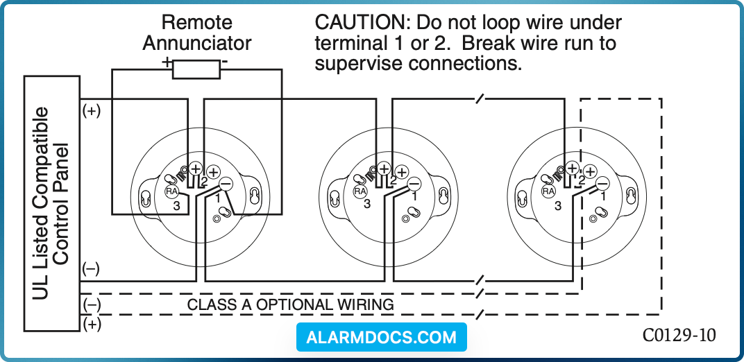
- 1. Wire the sensor base (supplied separately) as shown in the wiring diagram. (See Figure 2.)
- 2. Set the desired address on the sensor address switches. (See Figure 1.)
- 3. Install the sensor into the sensor base. Push the sensor into the base while turning it clockwise to secure it in place.
- 4. After all sensors have been installed, apply power to the control panel and activate the communication line.
- 5. Test the sensor(s) as described in the TESTING section of this manual.
FIGURE 2. WIRING DIAGRAM:
TAMPER-RESISTANCE
Intelligent photoelectric smoke sensors include a tamper-resistant capability that prevents their removal from the base without the use of a tool. Refer to the base manual for details on making use of this capability.
TESTING
Before testing, notify the proper authorities that the system is undergoing maintenance, and will temporarily be out of service. Disable the system to prevent unwanted alarms.
All sensors must be tested after installation and periodically thereafter. Test-ing methods must satisfy the Authority Having Jurisdiction (AHJ). Sensors offer maximum performance when tested and maintained in compliance with NFPA 72.
The sensor can be tested in the following ways:
A. Functional: Magnet Test (P/N M02-04-01 or M02-09-00)
This sensor can be functionally tested with a test magnet. The test magnet electronically simulates smoke in the sensing chamber, testing the sensor electronics and connections to the control panel.
- 1. Hold the test magnet in the magnet test area as shown in Figure 3.
- 2. The sensor should alarm the panel.
Two LEDs on the sensor are controlled by the panel to indicate sensor status. Coded signals, transmitted from the panel, can cause the LEDs to blink, latch on, or latch off. Refer to the control panel technical documen- tation for sensor LED status operation and expected delay to alarm.
B. Smoke Entry
Sensitivity readings are available through the FACP. Refer to the manufac- turer’s published instructions for proper use.
Additionally, canned aerosol simulated smoke (canned smoke agent) may be used for smoke entry testing of the smoke detector. Tested and ap- proved aerosol smoke products are:
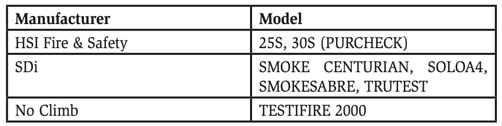
When used properly, the canned smoke agent will cause the smoke detec- tor to go into alarm. Refer to the manufacturer’s published instructions for proper use of the canned smoke agent.
A sensor that fails any of these tests may need to be cleaned as described under CLEANING, and retested.
When testing is complete, restore the system to normal operation and notify the proper authorities that the system is back in operation.