This Installation Guide provides step-by-step instructions for installing the Brivo Single Door Controller (SDC) single door access control device. Its primary audience is trained access control installation technicians (Installers) who are responsible for installing the Brivo SDC at client sites.
The guide is also intended for IT personnel. It may be used by dealers and their sales professionals to help them conduct pre-sales, and to provide client support during the installation process. Finally, it may be used for in-house training purposes and ongoing support.
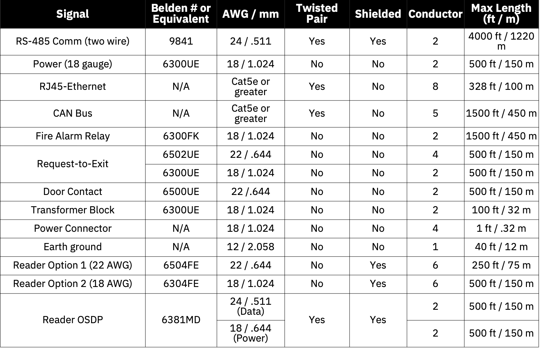
Wire Recommendations
PRE-INSTALLATION PROCEDURES
Before you begin installing the Brivo control panel, perform the following tasks to ensure a safe, speedy, and successful installation.
Understand the function of the Brivo SDC control panel
The Brivo Single Door Controller (SDC) is a one door control panel with a single access point. This control panel is considered a standalone system with internet connectivity to Brivo Access. The control board has one RS485 connection for one (or optionally two) OSDP reader connections. A second reader is supported for single door in/out antipassback configurations.
The Brivo SDC uses an on-board Ethernet PoE interface to communicate via any TCP/IP networking technology that can be connected through a hub, router or switch, including satellite communications. It is an IP-enabled Access Control System that interacts with the Brivo cloud server via the Brivo Access application.
Understand Brivo Brivo SDC product compatibility
The Brivo SDC control panel allows for the attachment of one primary and one additional OSDP reader directly to the Brivo SDC control panel for the purposes of in/out scenarios (antipassback). As such, the Brivo SDC is compatible with a large number of standard OSDP reader models. Brivo products are designed to accommodate the latest updates in OSDP using RS485 reader formats. The Brivo SDC control board is compatible with OSDP readers using RS485.
A current list of compatible readers and keypads is maintained on Brivo’s website at www.brivo.com. If you have a specific model of reader or keypad that is not listed on the Brivo website, please contact Technical Support at 1-866-BRIVO-4-U to determine compatibility.
Verify that the client site is ready to support the installation
1. Check with the IT department to ensure that the Brivo SDC to be installed is compatible with the company’s local area network (LAN).
- The Brivo SDC is equipped with a standard RJ45 socket that accepts a CAT5 cable with an RJ45 plug on any 10/100 Ethernet network. Physically connecting the panel is the same as plugging any computer or other device into the LAN.
- Refer to the Panel Networking Guide for instructions on connecting to the LAN. The Panel Networking Guide also contains a complete list of requirements regarding TCP/IP configuration parameters and information about security considerations.
2. Download the Brivo SDC Quick Start Guide from the Brivo website and provide it to the Primary Administrator. This document provides instructions for registering and configuring the control panel in the application.
3. Make sure the account has been created and the control panel is registered through Brivo. If the control panel has not been registered by the dealer, the installer may either contact Brivo Technical Support for assistance or simply register the panel directly.
4. Verify that the Primary Administrator and any other employee who will be accessing the system have Internet access on a computer equipped with a supported Web browser.
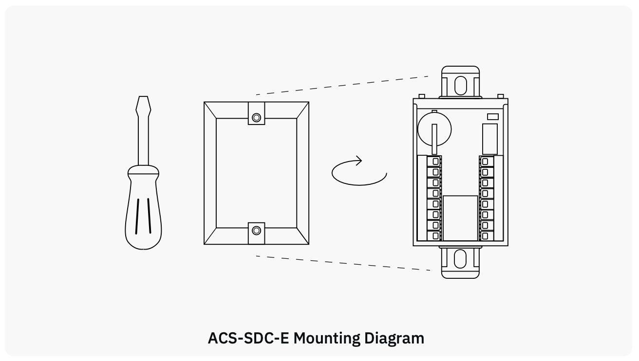
Assembling and mounting the ACS-SDC-E (without Enclosure)
Mount the ACS-SDC-E unit using the method described below:
1. This Single Door Access Control Device (ACS-SDC-E) is intended to be installed within the secure/protected area.
2. To mount the ACS-SDC-E: Fully wire the ACS-SDC-E, ensure all cables have proper strain relief, and use the provided zip tie for additional CAT5 or greater cable strain relief.
- Push the ACS-SDC-E into the junction box facing inwards.
- Attach the provided cover plate.
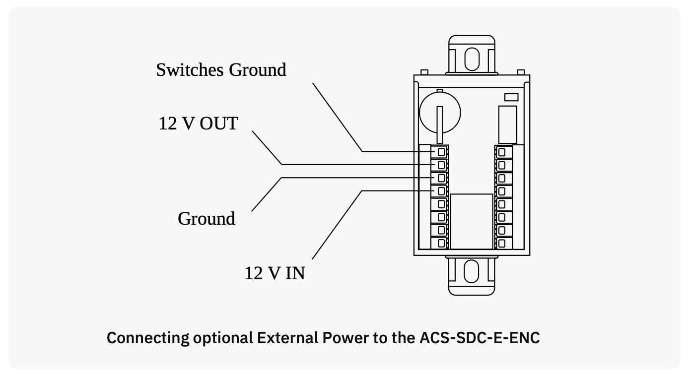
3. Use 18 AWG or 22 AWG wire (see table on Page 5) to connect the appropriate input power wires to the ACS-SDC-E unit.
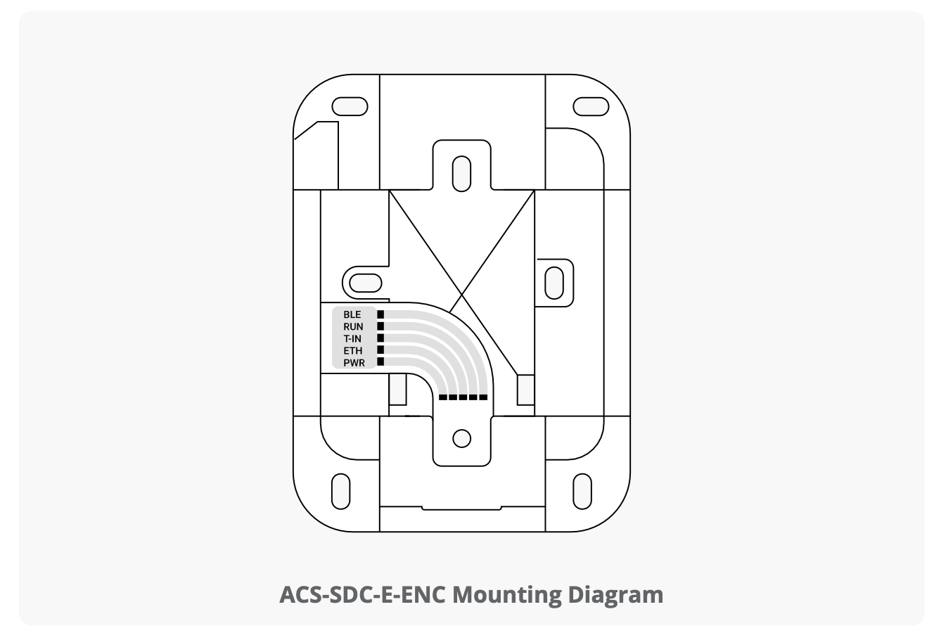
Assembling and mounting the ACS-SDC-E-ENC (with Enclosure)
Mount the ACS-SDC-E-ENC unit using the method described below:
1. This Single Door Access Control Device (ACS-SDC-E-ENC) is intended to be installed within the secure/protected area.
2. To mount the ACS-SDC-E-ENC:
- Fully wire the ACS-SDC-E-ENC, ensure all cables have proper strain relief, and use the provided zip tie for additional CAT5 or greater cable strain relief.
- Secure the enclosure to the wall using the provided screws.
3. Use 18 AWG or 22 AWG wire (see table on Page 5) to connect the appropriate input power wires to the ACS-SDC-E unit.
Battery
The model of coin cell battery of the Brivo SDC is CR1220 if a replacement is needed.
Tamper
When triggered, the Brivo SDC will generate a tamper event to Brivo Access. It will be visible in the real time event interface and can be configured to generate email notifications.
Tamper for ACS-SDC-E is motion triggered. Once triggered, the ACS-SDC-E will stop after a period of time (10 to 15 seconds) with the reader at rest.
Tamper for the ACS-SDC-E-ENC is a wired tamper attached from the Brivo SDC unit to the enclosure.
In order for the tamper alarm to be audible, an OSDP reader must be attached to the Brivo SDC unit and the tamper alarm will sound through the attached OSDP reader.
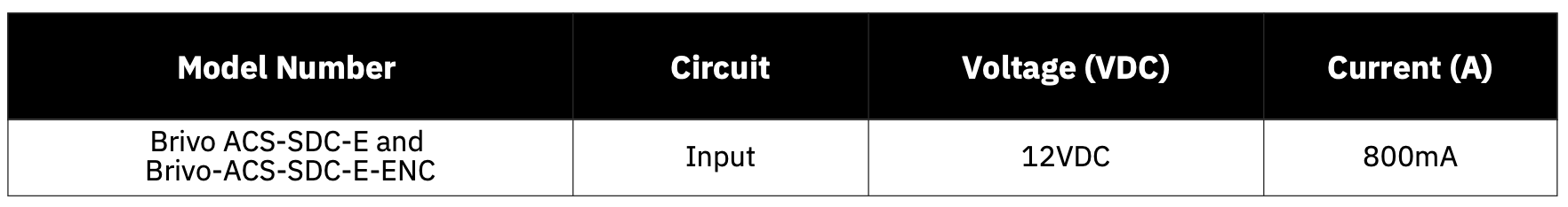
WIRING PROCEDURES
Provided below is the wire block diagram for the Brivo SDC unit.
For the Brivo SDC unit to be used for controlling a door, make the following connections:
1. DC Power In is rated from 10V DC to 15V DC. DC Power shall be provided through a UL294 approved Power Supply with Class 2 limited output..
2.Optionally power can be supplied through Power over Ethernet (PoE) through the RJ45 connector.
3. In the case of both DC power and PoE, the ACS-SDC-E will draw power from the DC power source.
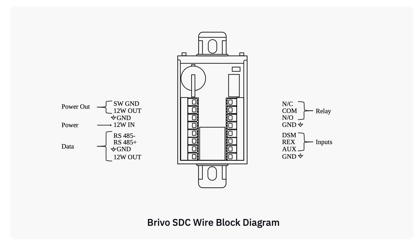
Lock Control
The Brivo SDC controls a single door lock through either a magnetic lock or door strike. There are two 12V DC outputs each capable of up to 500mA that can be used to power the door strike in conjunction with the lock control relay.
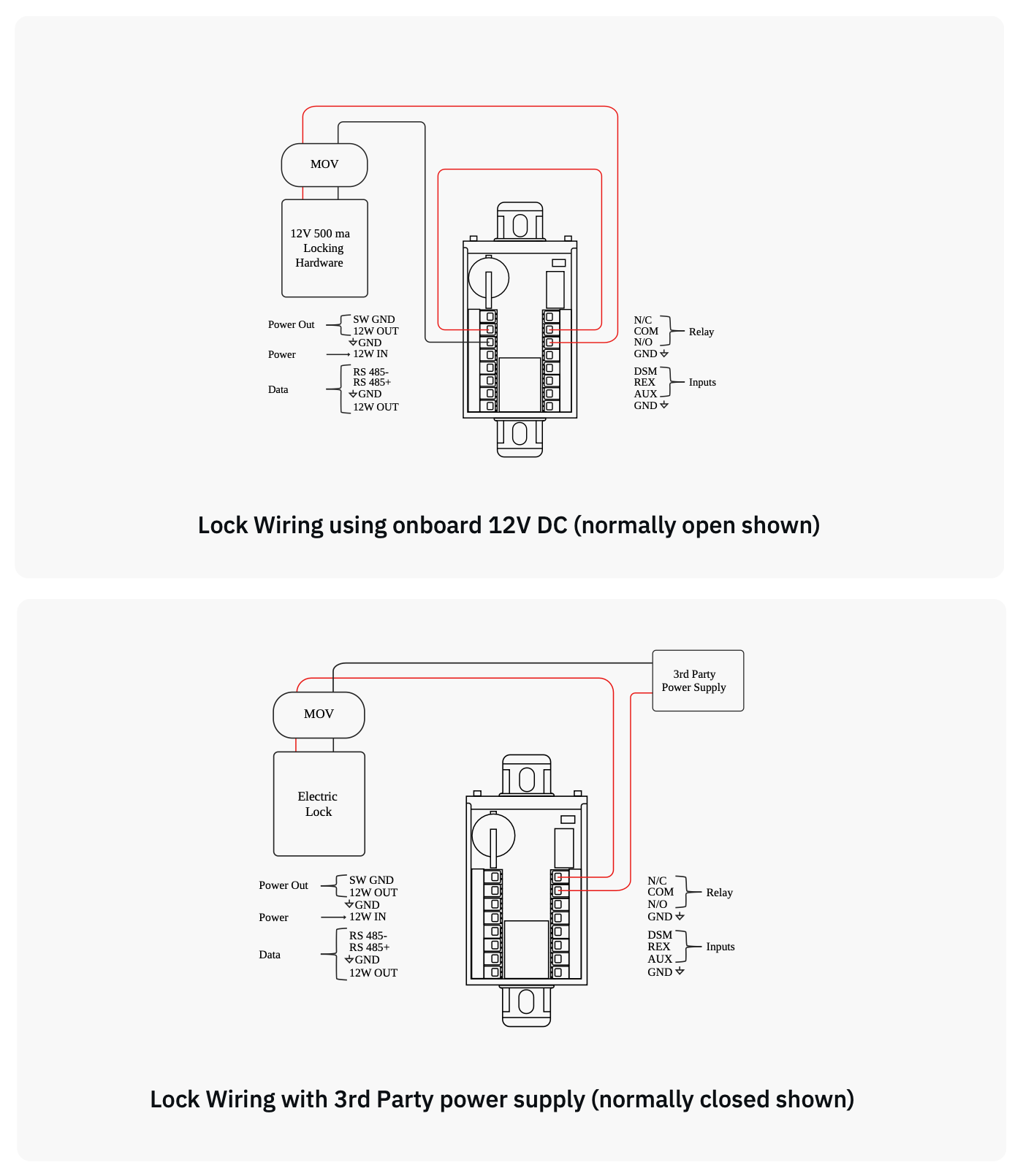
Lock Relay Output
The relay is rated up to 30V DC and 2A with 0.6 power factor. If power is provided via one of the Brivo SDC’s 12V outputs, the relay power would be 12V DC and the rated output of 500 mA of the Brivo SDC’s limited current. The Brivo SDC lock relay output has both Normally Open and Normally Closed contacts for wiring depending upon your application.
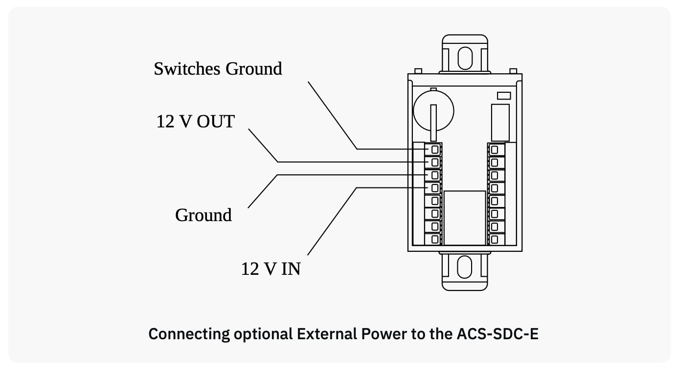
Switched Ground (Aux Output)
Switched Ground output enables or disables a Ground connection. This acts as a electronic relay switch to Ground.
1. Configure the default power as either Power-On or Default Power-Off through the Brivo Access Account Config Tool.
Supervised Inputs
1. There are three (3) Supervised Inputs:
- Request To Exit (REX)
- Door Switch Monitor/Door Contact (DSM)
- Auxiliary Input (AUX).
The Inputs can be configured as:
- Two (2) State (non-supervised) with Closed / Open Status.
- Four (4) State (use of two 2Kohm End of Line Resistors) supervised with Closed / Open / Short / Cut Status.
2. If used, wire the Aux Input using the Aux wire and the Ground wire. The Aux Input can be used for a variety of purposes, and is programmed through the Brivo Access Account Config Tool.
Wire the Reader
The Brivo SDC communicates to external readers through OSDP. One of the 12V DC outputs can be used to power the OSDP Reader(s) up to 500mA.
1. Connect RS485- and RS485+ for reader to Brivo SDC.
2. Connect the power wire to 12V Out and GND.
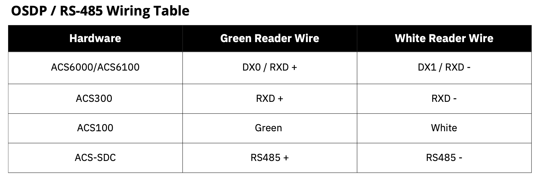
IMPORTANT RS485 WIRING INFORMATION
Ground the Brivo SDC
1. When grounding the Brivo SDC unit, use 18 AWG or larger wire to connect the Brivo SDC to a suitable earth ground.
2. The ground contact point is the GND contact located directly on the Brivo SDC unit.
Power up the Brivo SDC
1. Ensure that all wiring is complete prior to powering up the Brivo SDC unit.
2. Plug the CAT5 or greater cable into the LAN/PoE connector.
3. If not using PoE, plug in power to the Brivo SDC unit using 12V In and Ground.
4. Optionally, you may use PoE and an external 12V power supply for redundant simultaneous power input.
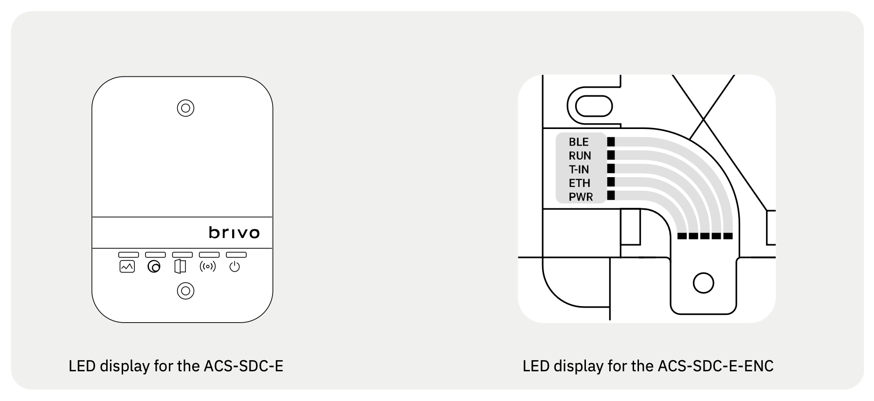
LED behavior for the ACS-SDC-E and ACS-SDC-E-ENC
The Brivo SDC unit has five LEDs with the following colors and functions
1. Power (PWR) – [GREEN]
2. Network Link (ETH) – [GREEN].
3. LED3 (T-IN) [RED] : OSDP Reader State Blink / Factory Reset
4. LED2 (RUN) [GREEN] : PCS Connection Solid ON/OFF
5. LED1 (BLE) [BLUE] : Heartbeat Blink
The ACS-SDC-E uses icons and can be seen with wall plate cover.
The ACS-SDC-E-ENC uses light pipes but cannot be seen with cover on. The front cover must be removed to see LEDs.
Resetting the Brivo SDC to factory default
The Brivo SDC unit goes into a factory default reset sequence when the following steps are performed:
1. Press and hold the factory default reset (FDR) button for ten (10) seconds and wait for the solid red LED to light up and stay solid.
2. Release the button within three (3) seconds.
3. After releasing the button, the Brivo SDC unit will recognize that a factory reset is desired and will initiate the factory default reset procedure. As the Brivo SDC unit restarts, the firmware will automatically update. Once LED operation returns to normal, the Brivo SDC unit will have been reset.
CONFIGURATION PROCEDURES
If any manual configuration is required, connect a laptop to the same local area network as the Brivo SDC unit
1. Set your NIC interface on your laptop/PC to IP 169.254.242.122 and net mask 255.255.255.0 .
2. Connect the CAT5 or greater cable from the NIC interface on the laptop to the PoE network switch.
3. Connect another CAT5 or greater cable from PoE network switch to Brivo SDC unit.
4. Allow a few seconds for the Brivo SDC unit to boot up.
5. Open a web browser and navigate to 169.254.242.121 . When the prompt appears for username/password, use username cli and password new5cli.
- a. The Administrative Interface (WebCLI) is used to gain access to the onboard functionality for debugging and manual configuration utilities.
Verify connection of the LAN to the Brivo SDC
1. Using CAT5 or greater cable, connect the LAN to the Brivo SDC unit via its LAN port.
- a. The LAN port is a 10/100 Ethernet interface with an RJ45 jack for connecting the Ethernet port on the Brivo SDC to a Local Area Network in order for it to gain connectivity to the Internet.
- b. Use a straight, (i.e., non-crossover) cable to connect this port to a local hub, switch or router.
2. Verify the connection of the LAN to the Brivo SDC by accessing the Administrative Interface (WebCLI) Using the instructions listed in the previous step. On the main page of the Administrative Interface, you should see a recent time/date stamp in the Last Contact with Central field.