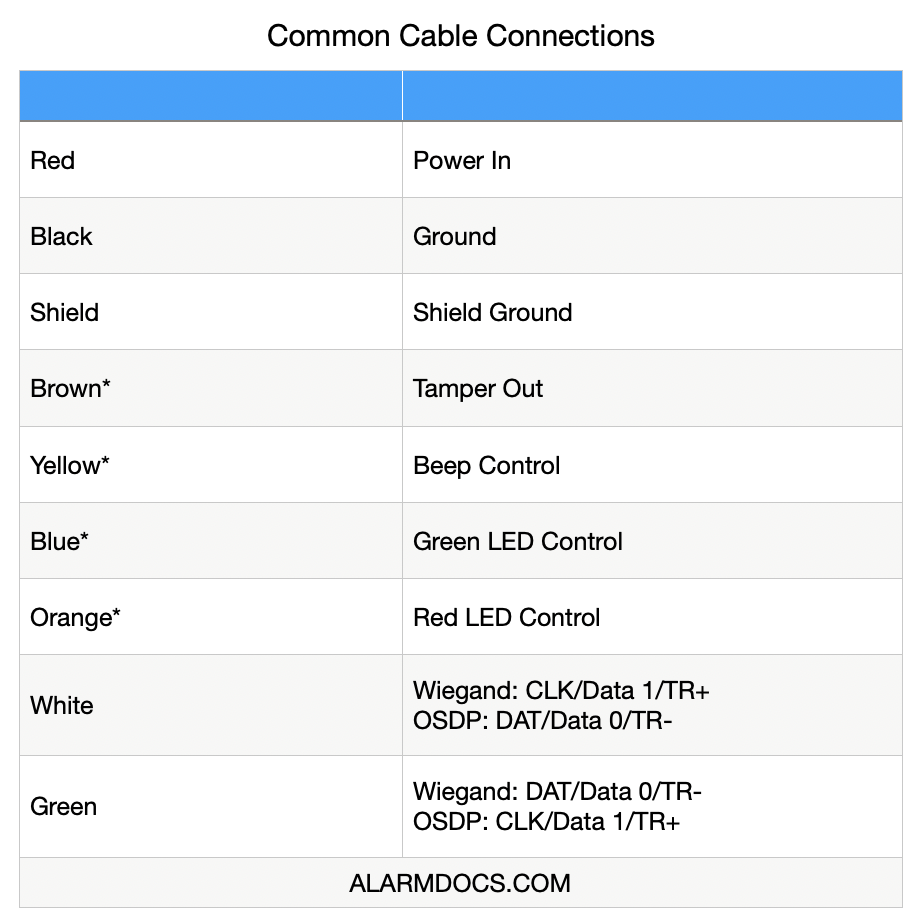
The Single Gang Reader with Keypad (ADC-AC-ET25) offers a modern aesthetic and a state-of-the-art feature set. Standard technologies include Proximity (125 kHz), NFC (13.56 MHz), and Bluetooth. The Single Gang Reader with Keypad is fully OSDP compliant and is enabled for Secure Channel. Additionally, the reader offers a patented feature called OSDP Auto-Detect. The reader communicates OSDP and Wiegand over the same wires to automatically detect and convert to OSDP Secure Channel protocol, eliminating the need to rewire or reconfigure the reader.
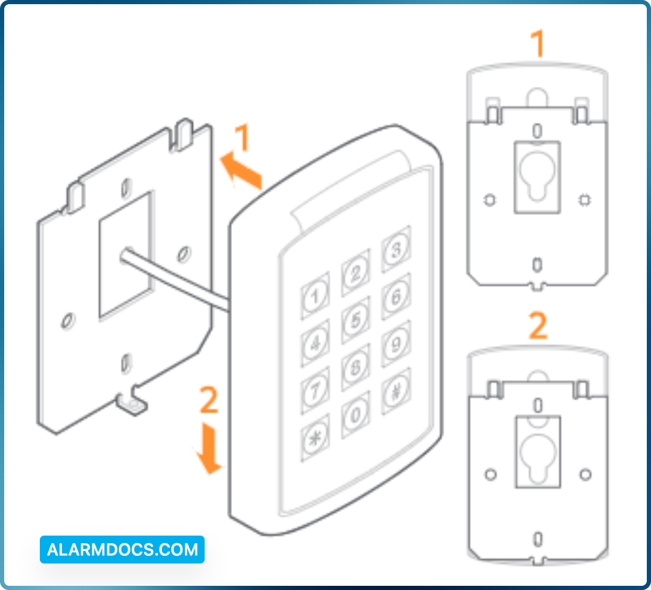
Mount the wall plate
Connect the wall plate to the single gang box using the provided #6 screws. Alternatively, the reader can be mounted using the provided #4 screws in the four outer holes for other installation requirements. Drywall installations will require molly bolts.
Wire the reader
Max Length to Panel
| 200′ (60 m) | 22 |
| 300′ | 20 |
| 500′ | 18 |
OSDP 9600 Baud Power 12 VDC
| Length | AWG |
| 1000′ | 22 AWG Twisted Pair |
Current @ 12 V and 25 C
| Avg. mA | Max. mA |
| 143 | 193 |
Secure the reader to the wall plate
- Align the reader so that the tabs of the base plate slide into the slots on the wall plate.
- Slide the reader into position.
- Secure the reader to the mounting plate using the supplied #4-40 screw or pin-in-Torx.
Power and test the reader
Power the reader and wait for the power-up LED beep sequence to complete. Present a valid credential to the reader and the light bar will turn green. If the test fails, check the wiring.
Installation tips
- When connecting the reader to a Wiegand panel, connect the Green wire to Data 0 and the White wire to Data 1.
- When connecting the reader to an OSDP panel, connect the Green wire to RS485A, and the White wire to RS485B.
- For an OSDP system, verify that the panel is successfully communicating with the reader prior to reading a badge or pressing a key.
Set the reader for Wiegand or OSDP
The process for setting a reader for Wiegand or OSDP varies depending on the firmware version.
Firmware Version 3.0.1.0
- By default, the reader will transmit credential and keypad data in Wiegand communication mode.
- Upon each power-up and before the reader reads a credential or a key is pressed, the reader will listen for an incoming OSDP message. If a message is received during this period, the reader will automatically switch to OSDP- only communication mode.
- To return to OSDP auto-detect mode (i.e., default mode), tilt the reader 45 degrees to simulate tamper and cycle power in this state. The power-up sequence should indicate OSDP auto-detect with 4 beeps.
Firmware Version 4.0.0.0 – 4.0.4.0
- By default, the reader will transmit credential and keypad data in Wiegand communication mode.
- Upon each power-up and before the reader reads a credential or a key is pressed, the reader will listen for an incoming OSDP message. If a message is received during this period, the reader will automatically switch to OSDP- only communication mode.
- To return to OSDP auto-detect mode (i.e., default mode), use the following steps:
1. Present a valid credential (i.e., any credential that the reader can pick up) to the face of the reader and hold it there.
2. Power cycle the reader while holding the card against the face of the reader.
3. After the normal startup A/V sequence (based on the current configuration) the LED should turn purple after a few seconds.
4. After seeing the purple LED, remove the card and power cycle the reader. The reader should boot back into default mode (i.e., Wiegand).
Firmware Version 4.1+
To return to Wiegand/Auto-Detect mode, use the following steps:
- Reset reader power, wait for the reader to complete its startup sequence and return to an idle state.
- Within 1 minute, present the desired configuration card to the reader.
- The reader should beep three times followed by a reset.
- When the reader has fully restarted, the new configuration will be applied.
Reader Startup Sequence
Upon a power reset, the Alarm.com Readers provide a reset sequence using the LED indicator and the beeper, to provide information about the reader type and its communication mode. The first sequence (sequence A) describes the credential technologies built-in the reader. First, a silent LED sequence will indicate the supported RF protocols. Both LEDs turn off for 250 milliseconds.
| Bluetooth | NFC | Prox |
| Beeper Silent, Red LED on for 500 milliseconds | Beeper Silent, Green LED on for 500 milliseconds | Beeper Silent, Amber LED on for 500 milliseconds |
After the above sequence identifies the supported RF protocols, the reader will then indicate the supported host communication using beep/flash sequences. Then the beeper and both LEDs will turn off for 250 milliseconds.
| Wiegand | OSDP | Auto-Detect |
| Beep and Blink Red LED once for 200 milliseconds | Beep and Blink Green LED twice for 200 milliseconds each | Beep and Blink Green LED 4 times for 200 milliseconds each |
Keypad Mode Setup
Within 1 minute of reader reset, enter the keypad config code: [*][88889999]. The reader will beep three times and the LED will flash amber for each beep. Within 2 seconds of entering the keypad config code, press the corresponding keycode below for the desired format. The reader will then beep three times and the LED will flash amber for each beep.
| 4-Bit Burst | 26-Bit Card Emulators |
| [*][4] | [#][0][7][7] |