The 736V V‑Plex® Module allows technicians to replace Honeywell® VISTA® FB Series panels with DMP XR150/XR550 Series panels without requiring the replacement of serial number addressable V‑Plex devices.
When connected to an XR150/XR550 Series panel, the module converts V‑Plex devices to DMP LX‑Bus zones.
Each 736V supports up to 96 V‑Plex devices. To add more devices to a system, connect a second module to another LX‑Bus and second polling loop circuit.
Compatibility
- XR150/XR550 Series Panels with Firmware Version 191 (7/2/19) or Higher
- V‑Plex devices with serial number addresses. One zone is supported per serial number. For a list of compatible V‑Plex devices, refer to Compatibility.
Installation
FIND V-PLEX DEVICE SERIAL NUMBERS
Before removing the Honeywell VISTA control panel and cabinet, you can retrieve a list of V‑Plex device serial numbers and names from the panel with Honeywell’s Compass® remote programming software. Printing V‑Plex device information will be helpful when programming the devices into the panel and will reduce programming time. Serial numbers are also printed on each V-Plex device.
If you don’t have access to the device serial numbers, click here to read advanced guide.
MOUNT THE 736V
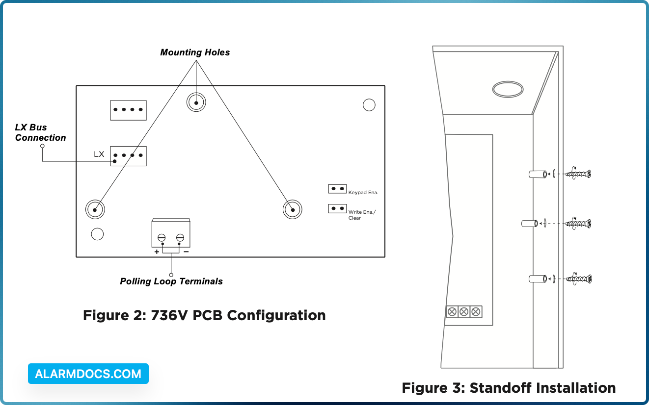
After replacing the Honeywell VISTA control panel and cabinet with an XR150 or XR550 Series panel and DMP enclosure, mount the module in the enclosure using the standard 3‑hole mounting pattern. Refer to Figure 2 and Figure 3 as needed during installation.
- Hold the plastic standoffs against the inside of the enclosure side wall.
- Insert the included Phillips head screws from the outside of the enclosure into the standoffs. Tighten the screws.
- Carefully snap the module onto the standoffs.
WIRE THE 736V
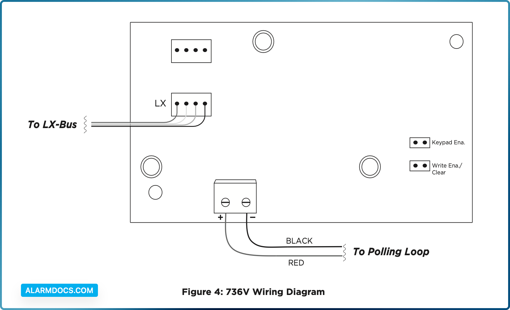
The 736V requires wiring connections from the LX header and polling loop terminals. Refer to Figure 4 when wiring the module.
- Use the Model 330 4‑wire harness to connect the module LX header directly to a panel LX‑Bus header. This connection allows the module to communicate with the panel and receive 12 VDC power.
- Short the two V‑Plex polling loop wires by touching them together for approximately 30 seconds.
- Connect the red wire from the polling loop to the positive module terminal. Connect the black wire from the polling loop to the negative module terminal.
- Remove both jumpers from Keypad Ena and Write Ena/Clear, then power up the panel.
PROGRAM THE PANEL
Set the 736V Address
On XR550 panels, connect a 736V to any LX‑Bus. V‑Plex devices are addressed on one LX‑Bus per loop. On XR150 panels, address 501 is reserved for the 736V.
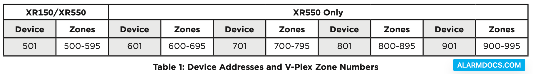
Unused zones on an LX‑Bus connected to a 736V can be used for any non‑polling loop devices except access control devices. See Table 1 for more information about device addresses and zones.
After completing each of the following steps, press CMD to advance to the next option.
1. Reset the panel. Enter 6653 (PROG) at the panel keypad and go to DEVICE SETUP.
2. At DEVICE NO, enter the device number of the LX‑Bus slot taken up by the module.
3. If the LX‑Bus already has zones programmed, ZONES PROGRAMMED CONTINUE? NO YES displays. To continue programming, select YES.
4. At DEVICE NAME, enter a name for the module.
5. (XR550 only) At DEVICE TYPE, select VPX.
Program V‑Plex Zones
After completing each of the following steps, press CMD to advance to the next option.
- 1. Go to ZONE INFORMATION.
- 2. At ZONE NO, enter the device zone that corresponds to the LX‑Bus.
- 3. At *UNUSED*, enter the zone name.
- 4. At ZONE TYPE, select the zone type.
- 5. At the Area Assignment section, select the area.
- 6. At the NEXT ZN? prompt, select NO.
- 7. At the DMP WLS? NO YES prompt, select NO.
- 8. At VPLEX DEVICE SERIAL#, enter A followed by the 7‑digit serial number.
- 9. At the NEXT ZN? prompt, select YES.
- 10. Repeat steps 2 through 10 for the remaining devices.
- 11. To save panel programming, go to STOP and press CMD.
Turn on Outputs
Smoke and PIR motion detector zones require that the output corresponding to the programmed zone are turned on to report the status correctly. For example, if you have a PIR on zone 503, output 503 will need to be toggled on for the zone to report correctly.
Go to the User Menu, enter a valid code that has output authority. Go to OUTPUTS ON/OFF? and enter the output number that corresponds to the zone. Select top row key 3 to toggle the output ON.
TEST THE 736V
Perform a Burglary Zone Walk Test to confirm that all of the devices are properly configured and communicating with the panel.
- 1. Reset the panel.
- 2. At a keypad, enter 8144 (WALK) and select BG.
- 3. Trip each zone on the system for 1 to 2 seconds. The keypad will annunciate each time a zone is tripped
- and display the number of zones successfully tripped.
- 4. Press the fourth select area or key to end the Walk Test.
ADDITIONAL INFORMATION
Diagnostic LEDs
The module has two onboard LEDs. The green LED indicates connection to the LX‑Bus and should flash once every two seconds. The yellow LED indicates that polling loop devices are communicating with the module.
Reboot the 736V
Before rebooting the module, remove the jumper from the Write Ena/Clear pins. To reboot, turn the last LX‑Bus output off, then back on. For example, if the module is connected to LX500, turn output 599 off then on.
Reuse a 736V V‑Plex Module
Before reusing a 736V, disconnect all zones. Delete all data in the module by placing the jumper across both Write Ena/Clear pins and powering up the panel.
Take Over with 4190SN or 4193SN
When taking over a 4190SN or 4193SN, only the loop 1 zone will report through the 736V. For the loop 1 zone to report correctly on the 4193SN, the loop 2 wire (green) must be landed on the common wire (black).