The 734 Access Control Module allows you to use the powerful, built-in access control capability of DMP Panels using smartcard, proximity, mag stripe, or biometric readers and other compatible authentication devices.
Power Supply
The 734 operates at 12/24 VDC from the power supply supporting a door’s magnetic lock or door‑strike.
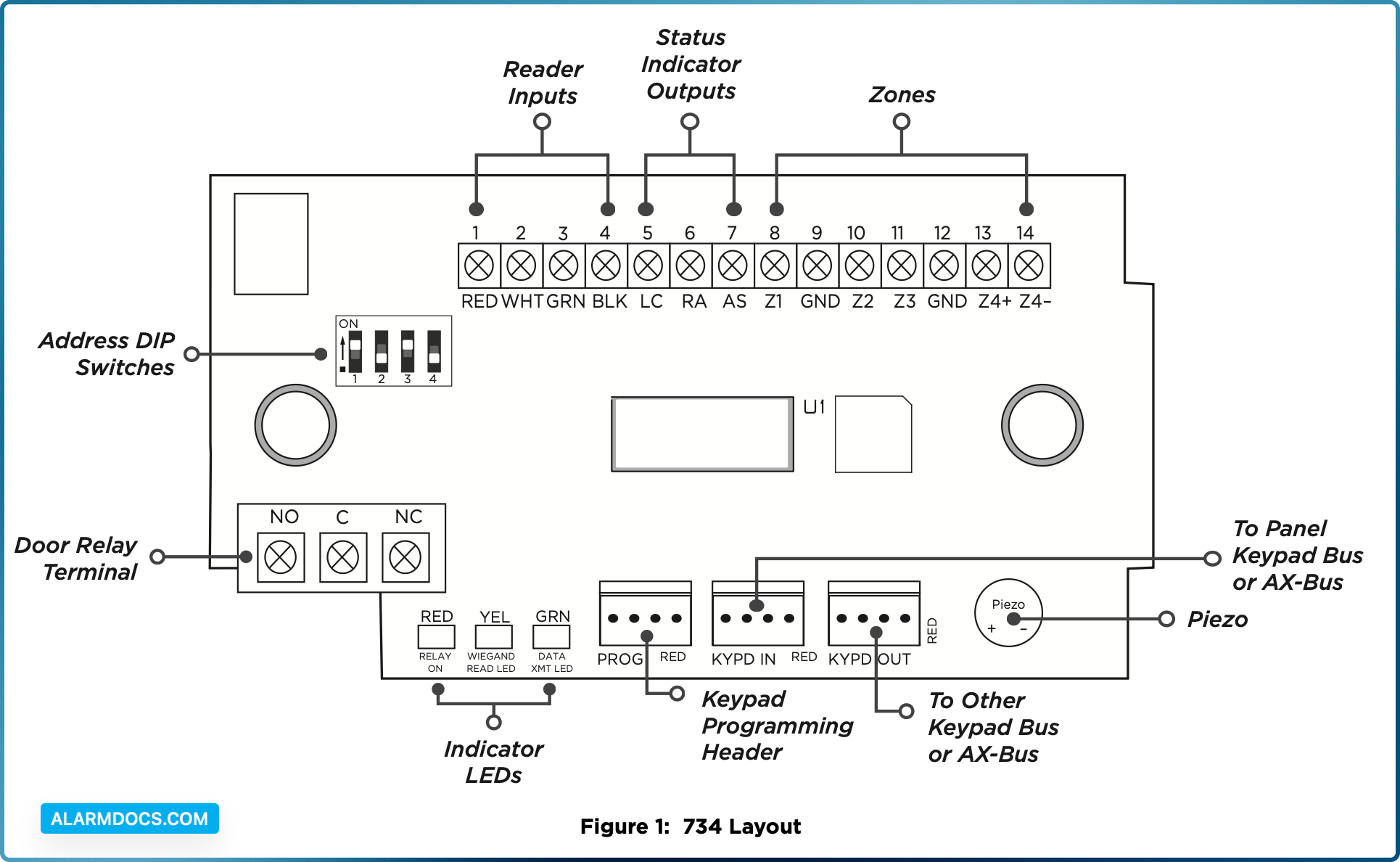
Zone Terminals
Zones 1, 2, and 3 on the 734 can be programmed for a variety of burglary or access control applications. Zone 4 is a class B, style A circuit that may be programmed as a fire zone.
Annunciators
An onboard programmable piezo provides local annunciation at the 734. You can also connect a variety of switched ground annunciators to the 734 for remote annunciation.
Indicator LEDs
The 734 provides three indicator LEDs:
- RELAY (red) turns on for the same duration as the door strike relay.
- WIEGAND (yellow) turns on for one second to indicate receipt of valid input.
- DATA (green) indicates that the module is communicating with the panel.
Form C Relay
The 10 Amp Form C relay draws up to 35 mA of current.
Programming Connection
The 734 provides a keypad programming connection that allows you to use a standard DMP LCD keypad for initial setup. Programming can be completed using a keypad connected to the 734 or from XR Series or XT75 Control Panels.
Wiegand and OSDP Reader Support
The 734 supports both Wiegand and OSDP card readers.
Keypad In and Out Connections
The Keypad In (KYPD IN) connection receives and transmits data to the panel Keypad Bus or AX‑Bus.
The Keypad Out (KYPD OUT) connection receives and transmits data out to other keypads or modules. Install a dual connector four‑position harness to allow daisy chain connection to other devices, up to the maximum number of devices supported. XT Series and XR150 Control Panels support up to 8 devices. XR550 Control Panels support up to 16 devices. When using the AX‑Buses with XR550 devices, you can have 32 doors, expandable to 96.
734 PCB FEATURES
INSTALL THE 734
Mount the 734
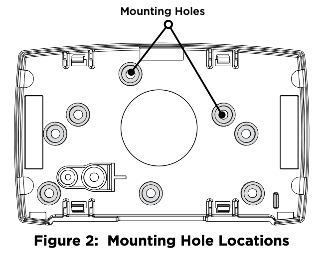
The module comes in a high‑impact plastic housing that you can mount directly to a wall, backboard, or other flat surface.
For easy installation, the back and ends of the 734 housing have wire entrances. The back also contains multiple mounting holes that allow you to mount the module on a single‑gang switch box. DMP recommends mounting the 734 near the protected door. Refer to Figure 2 for mounting hole locations on the housing base.
- 1. Remove the PCB from the plastic housing by loosening the clips on one side and gently lifting it out of the housing base.
- 2. Insert the included screws in the desired mounting hole locations and tighten them to secure the housing to the surface.
- 3. Reinstall the PCB in the housing base.
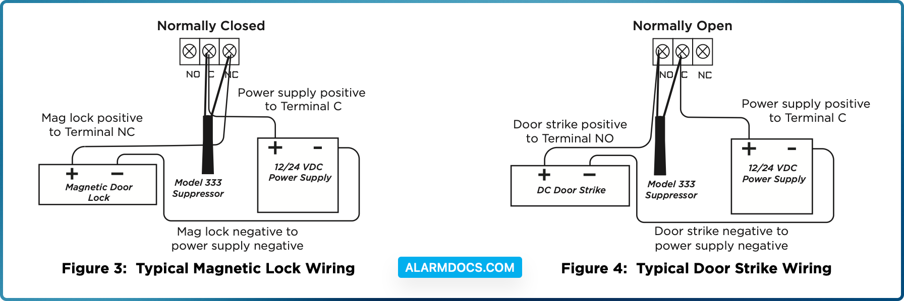
Wire the Access Control Lock
The 734 provides a Form C (SPDT) relay for controlling locks and other electronically‑controlled barriers. The three relay terminals marked NO C NC allow you to connect the device wiring to the relay for module control.
Use an additional power supply to power magnetic locks and door strikes. See Figure 3 and Figure 4 for typical magnetic lock and door strike wiring.
The Form C relay draws up to 35 mA of current and contacts are rated for 10 Amps (resistive) at 12/24 VDC. When connecting multiple locks to the Form C relay, the total current for all locks cannot exceed 10 Amps. If the total current for all locks exceeds 10 Amps, problems may arise and an isolation relay may be needed. Refer to “Isolation Relay (optional)” for more information.
Wire the 734
KYPD IN / KYPD OUT Connections
- KYPD IN (Keypad In): Receives and transmits data to the panel Keypad bus/AX‑Bus.
- KYPD OUT (Keypad Out): Receives and transmits data out to other keypad(s) or module(s). Install a dual‑connector harness to allow connection to other devices up to the maximum number of devices supported.
Status LEDs
The 734 board contains three status LEDs.
- The Red LED turns on for the same duration as the door strike relay.
- The Yellow LED turns on for one second to indicate receipt of a valid input determined by card formatprogramming.
- The Green LED indicates data sent to the panel.
Isolation Relay (Optional)
The Form C relay can control a device that draws less than 10 Amps of current. If a device draws more than 10 Amps of current, or the sum of all devices controlled by the Form C relay exceeds 10 Amps, an isolation relay must be used. Refer to Figure 5 and Figure 6 for isolation relay wiring.
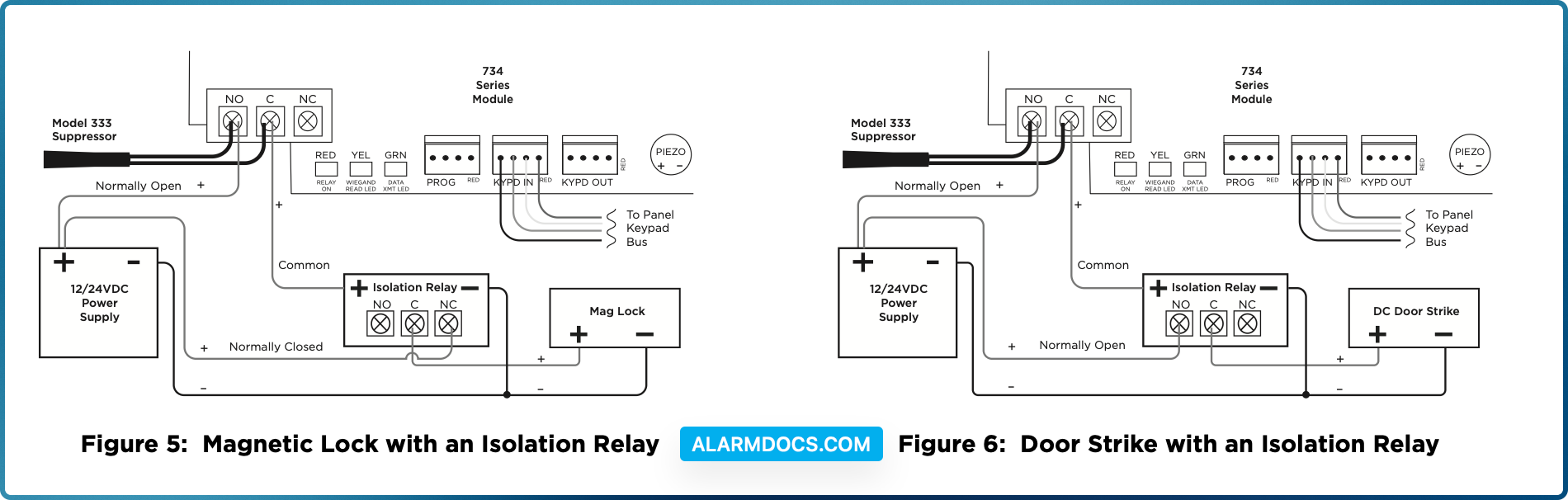
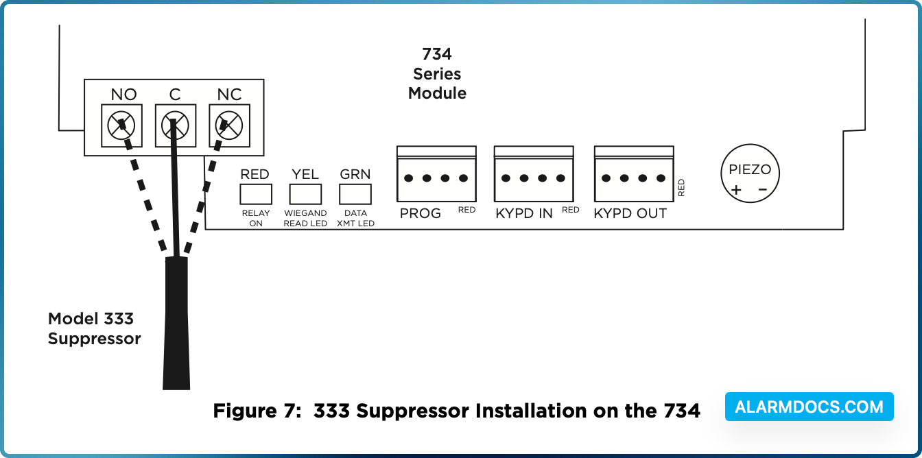
Install the 333 Suppressor
Use the included 333 suppressor with the 734 to suppress any surges caused by energizing a magnetic lock or door strike.
Install the 333 across the module’s C (common) and NO (normally open) or NC (normally closed) terminals.
If the device being controlled by the relay is connected to the NO and C terminals, install the suppressor on the NO and C terminals.
Conversely, if the device is connected to the NC and C terminals, install the 333 Suppressor on NC and C terminals.
The suppressor wire is non‑polarized. Install the suppressor as shown in Figure 7.
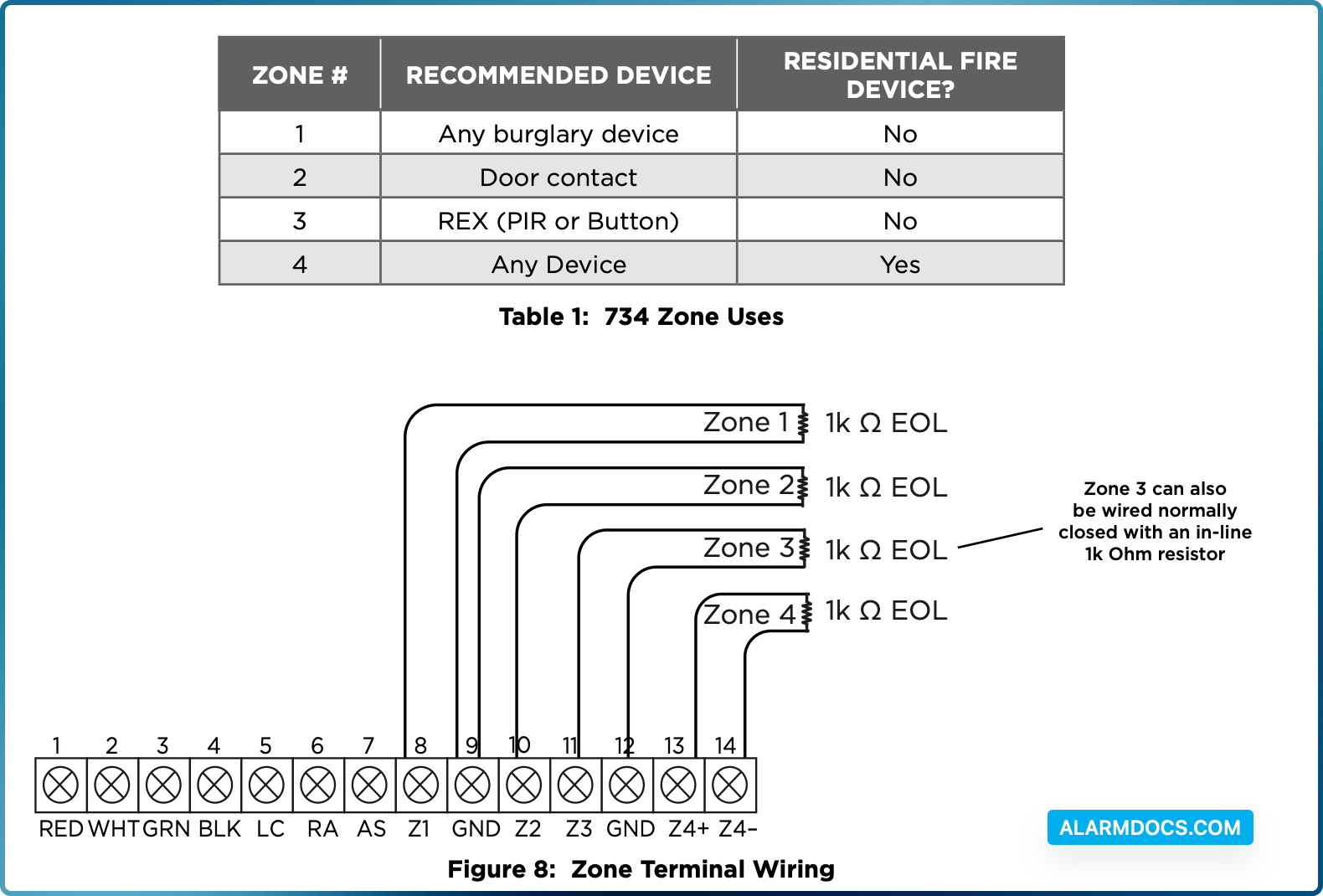
Wire the Zone Terminals
Terminals 8 through 12 connect grounded zones 1 through 3. These zones have a grounded side and cannot be used for fire‑initiating devices. Zones 2 and 3 can also be used for access control with zone 2 providing a bypass feature and zone 3 providing request to exit functionality.
Terminals 13 and 14 connect to zone 4. Zone 4 provides a non‑powered Class B ungrounded zone suitable for connection to fire devices such as heat detectors or pull stations.
Use the supplied 311 1k Ohm End‑of‑Line (EOL) resistors on each zone. Refer to the panel programming guide for programming instructions. See Table 1 and Figure 8 for more information on wiring the zone terminals.
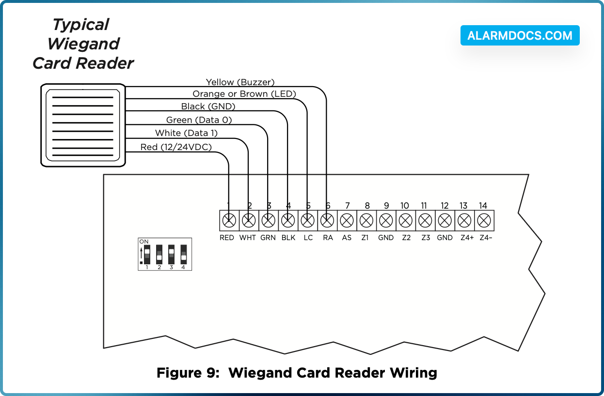
Connect a Wiegand Card Reader
The 734 provides direct 12/24 VDC output to the reader on the Red terminal connection. Figure 9 shows a reader with wire colors RED, WHT, GRN, and BLK connecting to Terminals 1, 2, 3, and 4.
The green wire carries Data Zero (D0), and the white wire carries Data One (D1). The red wire connects 12/24 VDC and the black wire is ground.
The wire colors may be different depending on the reader being installed. Refer to the literature provided with the reader for wire coding, wire distance, cable type (such as shielded), and other specifications.
Wiegand Status Indicator Outputs
Terminals 5, 6, and 7 provide connections for Remote LED Control, Remote Annunciation, and Armed Status indicators.
LC (Remote LED Control)
Remote LED Control provides an unsupervised switched ground for a visual indicator that turns on when the relay activates. Connect the wire from the LC Terminal to an LED. The LED turns on for the duration the door strike relay is on. HID readers optionally provide a connection for LED reader control.
RA (Remote Annunciation)
Remote Annunciation provides an unsupervised switched ground for a remote annunciator that turns on when the Zone 2 Bypass timer expires. Connect the wire from the RA Terminal to a remote annunciator. The remote annunciator silences when the RA restores. The remote annunciator (RA) switched ground operates even if the speaker is programmed not to operate.
AS (Armed Status)
Armed Status provides an unsupervised switched ground for a visual or audible armed status indicator that turns on when the burglary areas are armed, such as SYSTEM ON or ALL SYSTEM ON. Connect a wire from the AS Terminal to an armed status indicator.
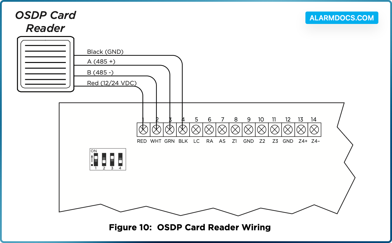
Connect an OSDP Card Reader
The 734 provides 12/24 VDC to the reader on the RED terminal connection and two‑way data transmission on the GRN and WHT connection. Only one OSDP reader can be connected to a module.
Use 24 AWG or larger two conductor RS‑485 cable to connect a reader to module terminals. For data transmission, connect the A (485 +) wire to the GRN terminal and the B (485 –) wire to the WHT terminal. For reader power, connect the red (DC +) wire to the RED terminal and the black (DC –) wire to the BLK terminal. Refer to Figure 10.
Wire colors may be different depending on the reader. Refer to literature provided with the reader for wire coding, distance, and other specifications.
OSDP Reader LED Operation
OSDP readers connected to 734 modules provide visual indication of relay condition, connection type, and encryption status with a red and green LED. Enable reader LED operation in LED CONTROL.
If enabled, the reader LED is turned on and operates the same as a Wiegand reader LED, lighting green when the module relay activates. Visual indication for connection and encryption status functions as follows:
- Fast blink (50 ms interval)—Connection secure, encrypted with 128‑bit AES and your custom secure key.
- Slow blink (100 ms interval)—Connection encrypted with the default SIA secure key.
The LED is not controlled by the device.
OSDP Reader Annunciation
OSDP readers connected to 734 modules provide audible indication of card reads. Enable reader annunciation in BUZZER CONTROL.
If enabled, the reader’s internal annunciator follows normal RA terminal operation.
If disabled, the reader’s internal annunciator will beep once when a credential is presented.
OSDP Status Indicator Outputs
Terminals 6 and 7 provide connections for Remote Annunciation and Armed Status indicators.
RA (Remote Annunciation)
Remote Annunciation provides an unsupervised switched ground for a remote annunciator that turns on when the Zone 2 Bypass timer expires. Connect the wire from the RA Terminal to a remote annunciator. The remote annunciator silences when the RA restores. The remote annunciator (RA) switched ground operates even if the speaker is programmed not to operate.
AS (Armed Status)
Armed Status provides an unsupervised switched ground for a visual or audible armed status indicator that turns on when the burglary areas are armed, such as SYSTEM ON or ALL SYSTEM ON. Connect a wire from the AS Terminal to an armed status indicator.
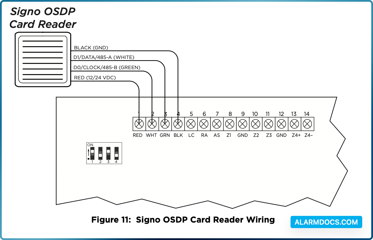
HID Signo OSDP Card Reader Wiring
When using OSDP mode on a HID Signo card reader, the typical wiring is switched. When using Wiegand mode, the wiring will stay the same.
The HID Signo card reader should be wired as follows:
- Red to Red
- Green to White
- White to Green
- Black to Black
Set the 734 Address
To set the 734 address, move the DIP switches on the PCB to the appropriate positions. See the following sections, Figure 11, and Table 2 to determine how to set Keypad Bus or AX‑Bus addresses.
Keypad Bus Addresses Explained
Each Keypad Bus address can accommodate one door output and four expansion zones. A 734 with an address of 2 on the Keypad Bus would represent door 2 and zones 21‑24. A 734 with a keypad address of 14 would represent door 14 and zones 141‑144.
AX‑Bus Addresses Explained
XR550 Control Panels are capable of access control expansion using any of the five AX/LX‑Bus headers (AX/LX500, 600, 700, 800, and 900). An AX‑Bus address can accommodate one door output and one expansion zone. Because the 734 has a built‑in four‑zone expander, three extra zones will be mapped to the 734 automatically.
A 734 with an address of 1 on AX500 would represent door 501 and zones 501‑504. A 734 with an address of 2 on AX500 would represent door 505 and zones 505‑508. A 734 with an address of 1 on AX700 would represent door 701 and zones 701‑704.
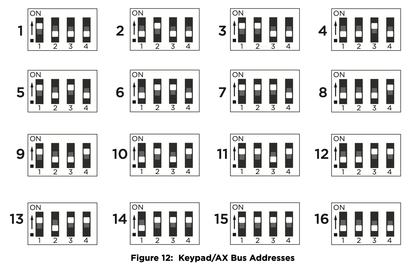
734 Address Table
To set the module’s address, move the DIP switches to the appropriate positions. See Figure 11 for Keypad Bus and AX-Bus DIP switch positions.

Connect the Power Supply
Power for the 734 can be provided by a 12 or 24 VDC power supply. The 12 VDC power can be provided by the panel keypad bus or from a separate power supply. The 24 VDC power supply can be connected directly to the relay terminal block (J1).