The 1132 is a wireless recessed contact that provides concealed protection for doors, windows, or any other application needing a discreet solution. As with all DMP 1100 Series transmitters, the onboard LED provides built‑in survey capability to allow for single‑person installations, eliminating the requirement for an external survey kit. The 1132 transmits Normal, Alarm, and Low Battery conditions.
PROGRAM THE PANEL
Refer to the panel programming guide as needed. After completing each of the following steps, press CMD to advance to the next prompt.
- At a keypad, enter 6653 (PROG) to access the Programmer Menu.
- At ZONE INFORMATION, enter the wireless zone number.
- At *UNUSED*, enter the zone name.
- At ZONE TYPE, press any select key or area and select the zone type.
- At AREA NO, enter the area number.
- At the NEXT ZN? prompt, select NO.
- When WIRELESS? displays, select YES.
- At SERIAL#, enter the eight‑digit device serial number.
- At SUPRVSN TIME, enter a supervision time. Default is 240.
- At the NEXT ZN? prompt, select YES if you are finished programming the zone. Select NO if you would like to access additional programming options.
- To save panel programming, go to STOP and press CMD.
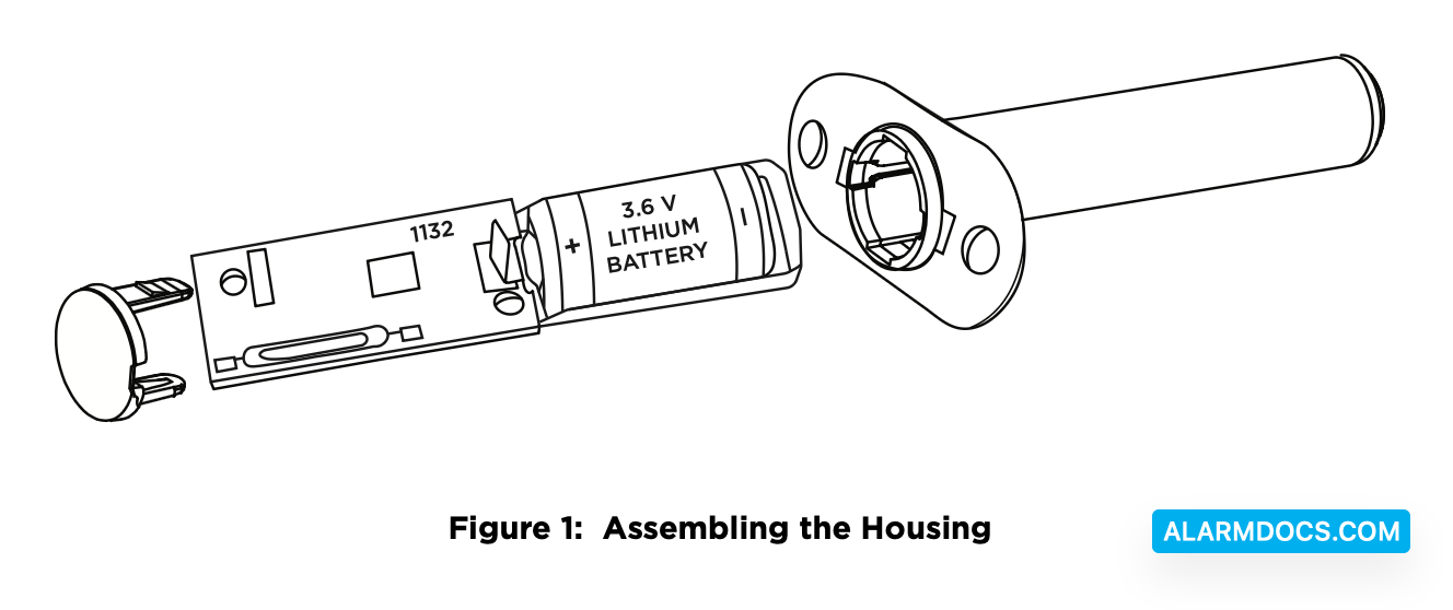
Install the Battery
DMP recommends PHD or SAFT brand 3.6V Lithium ½ AA batteries.
- Grasp the PCB and remove it from the housing.
- Place the battery into the battery tray with the positive end of the battery facing the transmitter PCB.
- Slide the battery tray and PCB into the housing.
- Install the cap on the transmitter housing tube.
Travel Distance
Faulted—A fault will be detected when the door is at 2 1/2 inches.
Restored—The fault will be restored when the door is at 1 1/2 inches.
Selection a Location
The 1132 provides a Survey LED capability to allow one person to confirm communication with the wireless receiver or panel while the cover is removed.
Move the magnet within 1/2 inch of the contact or pull it away from the contact to send data to the receiver.
For contact operation, the transmitter and magnet assembly should have no more than 1/2 inch between the housings after installation. When mounting on metal (ferrous) surfaces, this distance is slightly less. For door installations, it is recommended the transmitter be mounted in the door frame and the magnet assembly be mounted in the door. If the transmitter is installed in a metal door frame, the communication distance to the receiver may be reduced.
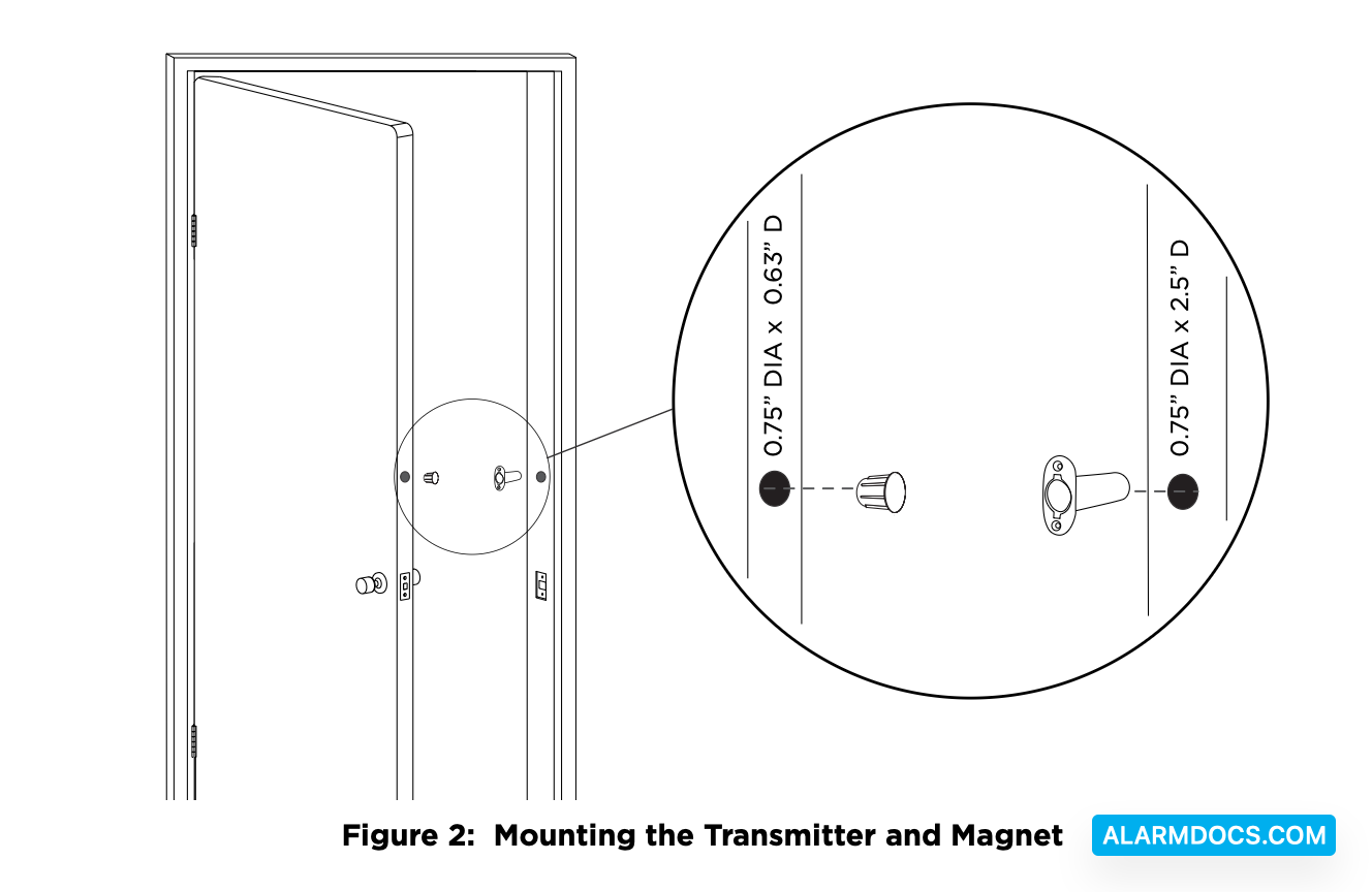
Mount the Transmitter and Magnet
1. To install the transmitter, use a 3/4 inch drill bit and drill a hole at least 2 3/4 inch deep in the frame at the desired location.
2. Insert the transmitter housing into the hole until the flange is flush with the door jamb.
3. To install the magnet, use a 3/4 inch drill bit, drill a hole at least 3/4 inch deep in the door edge at the desired location.
4. Insert the magnet into the hole and press it into place.
TEST THE TRANSMITTER
After the transmitter has been installed, test to confirm that it is communicating reliably with the panel. Complete the following steps to perform a Wireless Check-in Test from a keypad that is connected to the panel:
At the keypad, enter 8144 (WALK) and select WLS. If the transmitter fails to check in at the keypad, check for sources of interference such as metal objects and electronic equipment.
Supervision Time
When a receiver is installed, powered up, or the panel is reset, the supervision time for transmitters is reset. If the receiver has been powered down for more than one hour, wireless transmitters may take up to an additional hour to send a supervision message unless tripped, tampered, or powered up. This operation extends battery life for transmitters. A missing message may display on the keypad until the transmitter sends a supervision message.
Sensor Reset to Clear LOBAT
- Once the battery is replaced, a sensor reset is required at the keypad to clear the LOBAT message.
- On an LCD keypad, press and hold 2 for two seconds. On a graphic touchscreen keypad, press RESET. Enter your user code, if required. The keypad displays SENSORS OFF followed by SENSORS ON.