The 1117 Wireless LED Annunciator provides a remote red LED for visual indication of system status. The 1117 can be programmed for nearly any panel output option and can respond to conditions such as armed area annunciation, ambush alarm, burglary alarm, exit timer, entry timer, schedules, or communication failure.
PROGRAM THE PANEL
Program the 1117 in Output Options as an Arm-Alarm Output.
- In OUTPUT INFO, enter the OUTPUT number.
- Enter the OUTPUT NAME.
- Enter the eight-digit SERIAL# and press CMD.
- Enter the SUPRVSN TIME and press CMD.
- Press the back arrow when OUTPUT SETUP displays.
- Press CMD until STOP displays and then press any select area to save and exit programming.
Program Slow Response
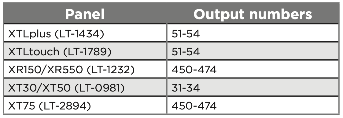
Use the following output numbers to indicate whether the wireless device responds within 15 seconds to trip the output (slow response).
Program Fast Response
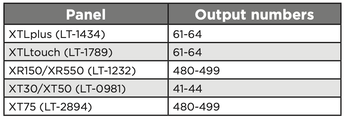
Use the following output numbers to indicate whether the wireless device responds within 1 second to trip the output (fast response).
- A receiver is installed, powered down, and powered up
- The panel is reset
- Programming is complete
POWER THE 1117
Power the 1117 with a 3 V lithium battery or a 12 VDC power supply. Do not install a battery if the 1117 is being powered by a power supply. The power supply does not charge the battery.
12 VDC Plug-In or External Power Supply
The 1117 can also be powered by a 12 VDC plug-in power supply (e.g. DMP Model 372-1000-W) or a 12 VDC external power supply (e.g. DMP Model 505- 12 or PS12-5). When using a plug-in power supply, mount the 1117 near a wall outlet.
- Remove the housing cover.
- Install the supplied jumper on the two pins next to EXT on the power source header.
- Wire the power supply to the DC power terminals by following the power supply-specific instructions below.
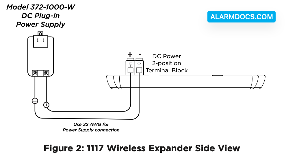
Plug-In Power Supply
- Using 22 AWG wire, connect the DC terminal (+) to the positive terminal on the power supply.
- Connect the DC terminal (-) to the negative terminal on the power supply. See Figure 2.
- Plug the power supply into a 120 VAC, 60 Hz dedicated outlet not controlled by a switch.
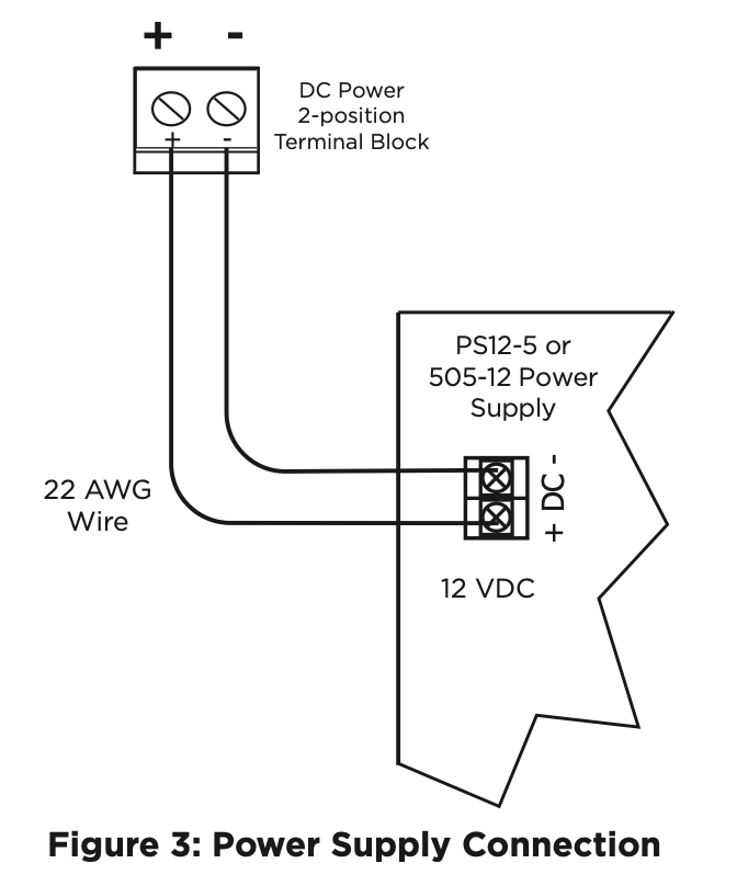
External Power Supply
- Using 22 AWG wire, connect the DC power terminal block on the device to the DC power terminal on the PS12-5 or the 505-12 power supply PCB.
- Observe positive and negative polarity on all connections. See Figure 3.
- Snap the cover back into place when you are finished.
SELECT A LOCATION
The 1117 provides a Survey LED capability to allow one person to confirm communication with the wireless receiver or panel while the cover is removed.
- With the cover removed, hold the 1117 in the exact desired location.
- Press the tamper switch to send data to the panel and determine if communication is confirmed or faulty.
MOUNT THE 1117
Mount the 1117 on a flat surface such as a wall or single-gang box. When using the optional Model 376L plug‑in power supply, mount the 1117 near a wall outlet. See Figure 4 for mounting hole locations on the housing base. You will need to remove the 1117 PCB from the housing base to reach some of the mounting hole locations.
TEST THE 1117
To test the 1117 from a keypad, access the User Menu Outputs On/Off option if the device is powered by a power supply. The device LED should light within 15 seconds of entering the assigned output number and selecting on.
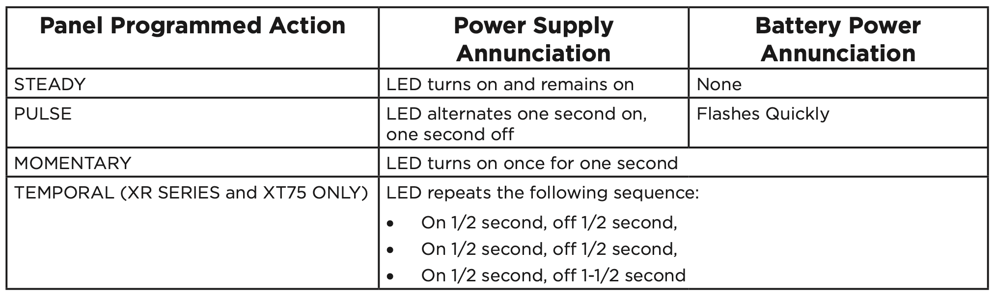
1117 LED Annunciation Operation
The 1117 LED annunciation differs based on whether it is powered by a battery or an optional power supply. When an optional power supply is connected, additional annunciations are available.
The follow table shows the 1117 LED annunciation operation options.