The 1116 Wireless Relay Output provides a Form C (SPDT) dry relay contact rated for 1 Amp at 30 VDC. Regardless of the state of the relay, the 1116 operates on constant minimal standby current.
The 1116 relay can be controlled from a DMP panel output programmed to respond to a variety of conditions such as armed area annunciation, ambush alarm, burglary alarm, exit timer, entry timer, schedules, or communication failure.
PROGRAM THE PANEL
- In OUTPUT INFO or OUTPUT SETUP, enter the OUTPUT number.
- Enter the OUTPUT NAME.
- Enter the eight-digit SERIAL# and press CMD.
- Enter the SUPRVSN TIME and press CMD.
- Press the back arrow when OUTPUT NO: displays.
- Press CMD until STOP displays and then press any select area to save and exit programming.
Program Slow Response
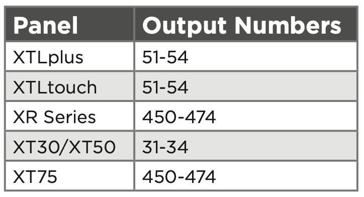
Use the following output numbers for your device to indicate whether the wireless device responds within 15 seconds to trip the output (slow response). Programming the 1116 as a slow response output can increase battery life. See last page for battery life expectancy.
Program Fast Response
Use the following output numbers for your device to indicate whether the wireless device responds within 1 second to trip the output (fast response). Programming the 1116 as a fast response output can decrease battery life. See last page for battery life expectancy.
Supervision Reset
Supervision time is reset under the following circumstances:
- A receiver is installed, powered down, and powered up
- The panel is reset
- Programming is complete
POWER THE DEVICE
Power the device with a 3 V lithium battery or a 12 VDC power supply. Do not install a battery if the device is being powered by a power supply. The power supply does not charge the battery.
CR123A 3 V Lithium Battery
Observe polarity when installing the included CR123A battery.
- Remove the housing cover.
- Install the supplied jumper on the two pins next to BAT on the power source header.
- Place the battery in the holder and observe polarity.
- Snap the cover back into place.
12 VDC Plug-In or External Power Supply
The device can also be powered by a 12 VDC plug‑in power supply (e.g. DMP Model 372-1000-W) or a 12 VDC external power supply (e.g. DMP Model 505-12 or DMP Model PS12-5). When using a plug-in power supply, mount the device near a wall outlet.
- Remove the housing cover.
- Install the supplied jumper on the two pins next to EXT on the power source header.
- Wire the power supply to the DC power terminals by following the power supply-specific instructions below.
Plug-In Power Supply
- Using 22 AWG wire, connect the DC terminal (+) to the positive terminal on the power supply.
- Connect the DC terminal (-) to the negative terminal on the power supply.
- Plug the power supply into a 120 VAC, 60 Hz dedicated outlet not controlled by a switch.
External Power Supply
- Using 22 AWG wire, connect the DC power terminal block on the device to the DC power terminal on the PS12-5 or the 505-12 power supply PCB.
- Observe positive and negative polarity on all connections.
- Snap the cover back into place when you are finished.
SELECT A LOCATION
The 1116 Wireless Relay Output provides a Survey LED capability to allow one person to confirm communication with the wireless receiver or panel while the cover is removed.
- With the cover removed, hold the device in the exact desired location.
- Press the tamper switch to send data to the panel and determine if communication is confirmed or faulty.
MOUNT THE DEVICE
Mount the device on a flat surface such as a wall or single-gang box. When using the optional Model 376L plug-in power supply, mount the device near a wall outlet. See Figure 4 for an example of all mounting holes on the housing base. Use any combination.
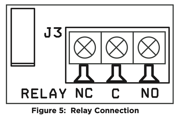
CONNECT THE DEVICE
Use 22 or 18 AWG wire to connect the relay output. The Form C relay can be connected to operate as Normally Closed (NC) or Normally Open (NO).
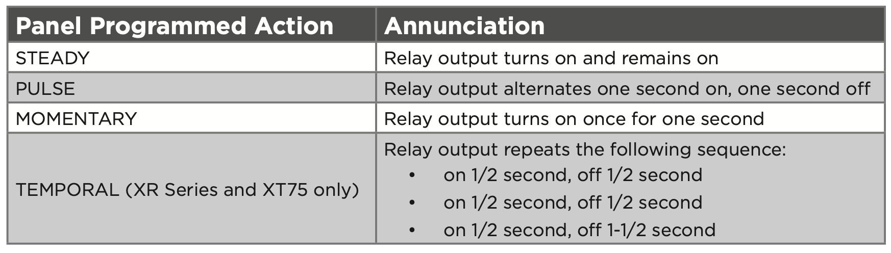
1116 Relay Output Annunciation
The following table shows the device annunciation operation options.