The 1112 Wireless Water and Temperature Detector is designed to monitor and protect areas from temperature fluctuations and water leaks.
The low-profile form factor transmitter includes built-in water probes and fits under most consumer household appliances. The 1112 has an internal temperature sensor that detects water leaks or cold and hot temperature ranges.
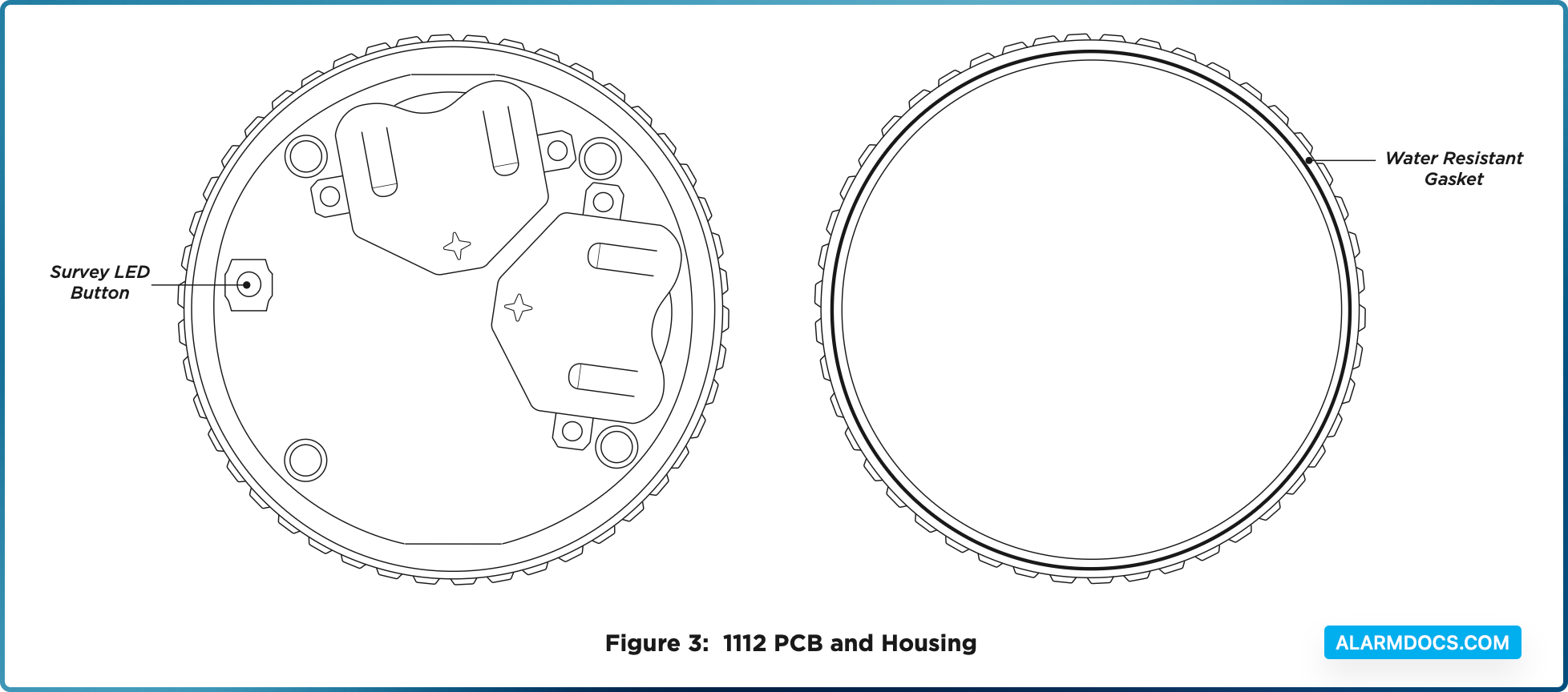
The transmitter includes a water- resistant gasket inside the top housing with metal contacts on the bottom housing for water sensing.
The transmitter can be programmed with up to three zones for temperature sensing, water detection, or both.
PROGRAM THE PANEL
The 1112 can be programmed with up to three zones. Refer to the panel programming guide as needed. After completing each of the following steps, press CMD to advance to the next prompt.

- At a keypad, enter 6653 (PROG) to access the Programmer Menu.
- At ZONE INFORMATION, enter the wireless zone number. Program 1112 zones sequentially. For example, program the first zone as 71 and the next zone as 72.
- At *UNUSED*, enter the zone name.
- At ZONE TYPE, press any select key or area and select SV (Supervisory) as the zone type.
- At the NEXT ZN? prompt, select NO.
- When WIRELESS? displays, select YES.
- At SERIAL#, enter the eight‑digit device serial number.
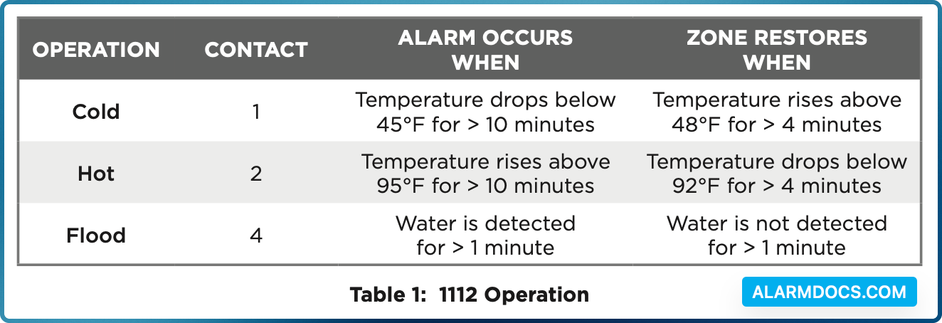
- At CONTACT, enter the appropriate contact number. Refer to Table 1.
- At SUPRVSN TIME, enter a supervision time. Default is 240.
- At the NEXT ZN? prompt, select YES if you are finished programming the zone. Select NO if you would like to access additional programming options.
To enable encryption, complete the steps below:
- Go to SYSTEM OPTIONS.
- At 1100 ENCRYPTION, select ALL to only add encrypted wireless devices to the system. Select BOTH to allow both encrypted and non-encrypted wireless devices to be programmed.
- The default passphrase is displayed at the ENTER PASSPHRASE prompt. Press CMD to keep the default.
- Press any select key or area to change the passphrase and enter an 8‑character hexadecimal string (0‑9, A‑F).
- To save panel programming, go to STOP and press CMD.
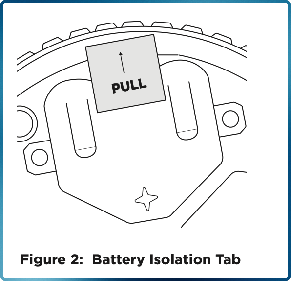
REMOVE THE BATTERY ISOLATION TAB
Twist the top housing counterclockwise until it separates from the bottom housing.
On the 1112 PCB, remove the two battery isolation pull tabs. When removed, the transmitter activates and may be programmed into the system. See Figure 2.
SELECT A LOCATION
The 1112 provides a survey LED capability to allow one person to confirm communication with the wireless receiver or panel while the cover is removed. Refer to Figure 3.
To perform the survey LED test, complete the following steps:
- With the cover removed, hold the transmitter in the exact desired location.
- Press the survey LED button to send data to the panel and determine if communication is confirmed or faulty.
TEST THE TRANSMITTER
To close the 1112 lid, align the top and bottom housings, then twist the top clockwise onto the bottom until both housings fit securely into place.
After the transmitter has been installed, test to confirm that it is communicating reliably with the panel. Complete the following steps to perform a Wireless Check-in Test from a keypad that is connected to the panel:
At the keypad, enter 8144 (WALK) and select WLS. If the transmitter fails to check in at the keypad, check for sources of interference such as metal objects and electronic equipment.
When the test is initiated, the panel automatically tests the communication between itself and each wireless zone. Wireless zones should not be manually tripped during this test. Manually tripping zones during this test could lead to a false failure.
ADDITIONAL INFORMATION
The 1112 operates in temperatures between 32°F and 120°F with a relative non-condensing humidity of 85%. Refer to Table 1 for 1112 operations.
Supervision Time
When a receiver is installed, powered up, or the panel is reset, the supervision time for transmitters is reset. If the receiver has been powered down for more than one hour, wireless transmitters may take up to an additional hour to send a supervision message unless tripped or powered up. This operation extends battery life for transmitters. A missing message may display on the keypad until the transmitter sends a supervision message.
Replace the Batteries
- 1. Twist the top housing counterclockwise until it separates from the bottom housing.
- 2. Remove the old batteries, observe polarity, and place the new batteries in the holder.
- 3. Align the top and bottom housings, then twist the top clockwise onto the bottom until both housings fit securely into place.
Sensor Reset to Clear LOBAT
- 1. Once the battery is replaced, a sensor reset is required at the keypad to clear the LOBAT message.
- 2. On an LCD keypad, press and hold 2 for two seconds. On a graphic touchscreen keypad, press RESET. Enter your user code, if required. The keypad displays SENSORS OFF followed by SENSORS ON.