Zone expansion modules allow you to increase the number of reporting zones available on DMP panels. Refer to the panel installation guide for more information about zone expansion modules and the maximum number allowed per panel. The modules connect to the panel 4-wire Keypad Bus or LX-Bus and are set to an address that determines the reporting zone number. The 711 provides one Class B zone.
The 711 housing mounts to any flat surface using the mounting holes provided in the base. Snap on the cover to complete the installation.
Install the Zone Expansion Module
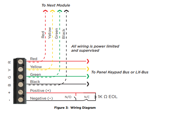
Wiring the 711 Zone Expansion Module
Connect the Red, Green, Yellow, and Black wires from the panel Keypad Bus or LX-Bus to the matching terminals or harness wires on the zone expander.
Wiring Specifications for Keypad and LX-Bus
DMP recommends using 18 or 22 gauge unshielded wire for all keypad and LX‑Bus circuits. Do not use twisted pair or shielded wire for LX-Bus and Keypad Bus data circuits. To maintain auxiliary power integrity when using 22-gauge wire do not exceed 500 feet. When using 18‑gauge wire do not exceed 1,000 feet. Install an additional power supply to increase the wire length or add devices.
Maximum distance for any one circuit (length of wire) is 2,500 feet despite the wire gauge or number of branches. Increased wire distance from the panel decreases DC voltage on the wire. Maximum number of devices per 2,500 feet circuit is 40.
Maximum voltage drop between the panel (or auxiliary power supply) and any device is 2.0 VDC. If the voltage at any device is less than the required level, add an auxiliary power supply at the end of the circuit. When voltage is too low, the devices cannot operate properly.
PROGRAM THE PANEL
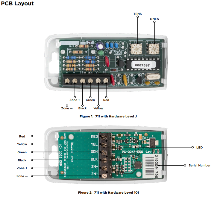
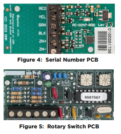
711 Zone Expansion Modules with Hardware Level J are programmed using two rotary switches to set the address of the expansion module. 711 Zone Expansion Modules with Hardware Level 101 are programmed using a 10-digit serial number. The following sections detail how to program each version.
Serial Number Programming
711 Zone Expansion Modules with Hardware Level 101 are programmed using the 10-digit serial number on the unit. This is done by navigating to Zone Information and entering the serial number at the Expander Serial Number prompt.
Rotary Switch Programming
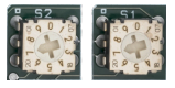
711 Zone Expansion Modules with Hardware Level J are programmed into the panel using two rotary switches identified as TENS and ONES to set the module address. Use a small screwdriver to set the address accordingly for Keypad Bus or LX-bus.
Address the Module
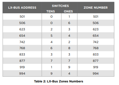
The 711 uses two rotary switches identified as TENS and ONES to set the module address. See LX-Bus Zone Numbers below for LX-Bus addresses and set the switches to match the last two digits of the address. For example, for address 502 on an XR550 Control Panel set the TENS switch to zero and the ONES switch to two.
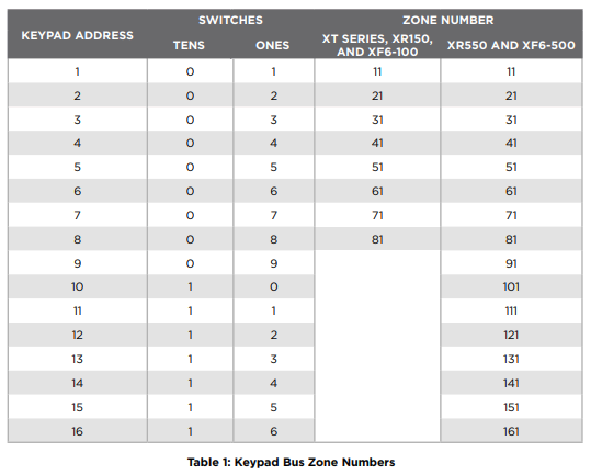
Keypad Bus Zone Numbers
The 711 only uses the first zone number on a keypad bus. The last three zone numbers cannot be used for other devices. Refer to Table 1 for Keypad Bus zone numbers and the panels where they operate.
LX-Bus Zone Numbers
Refer to Table 2 for a partial list of XR Series, XF6 Series Fire, and XT75 Control Panels LX-Bus zone numbers. Available addresses on XT75 Control Panels are 500-549. Available addresses on XR150 and XF6-100 Control Panels are 500-599. Available addresses on XR550 and XF6-500 Control Panels are 500-999.
REFERENCE
Zone Expansion Data LED
The zone expansion LED flashes each time the module responds to a poll from the panel. If there is a problem with the panel, panel programming, or the green data wire between the panel and the zone expansion module, the LED stops flashing and “System Trouble” appears in the keypad display.