If you don’t have access to a list of the V-Plex® device serial numbers from the VISTA® control panel that you intend to replace, you can use the 736V autolearn function and a keypad to retrieve the V-Plex device serial numbers. Before programming, refer to the 736V V-Plex Installation Guide (LT-1910) for mounting and wiring instructions.
Learn Devices into the 736V
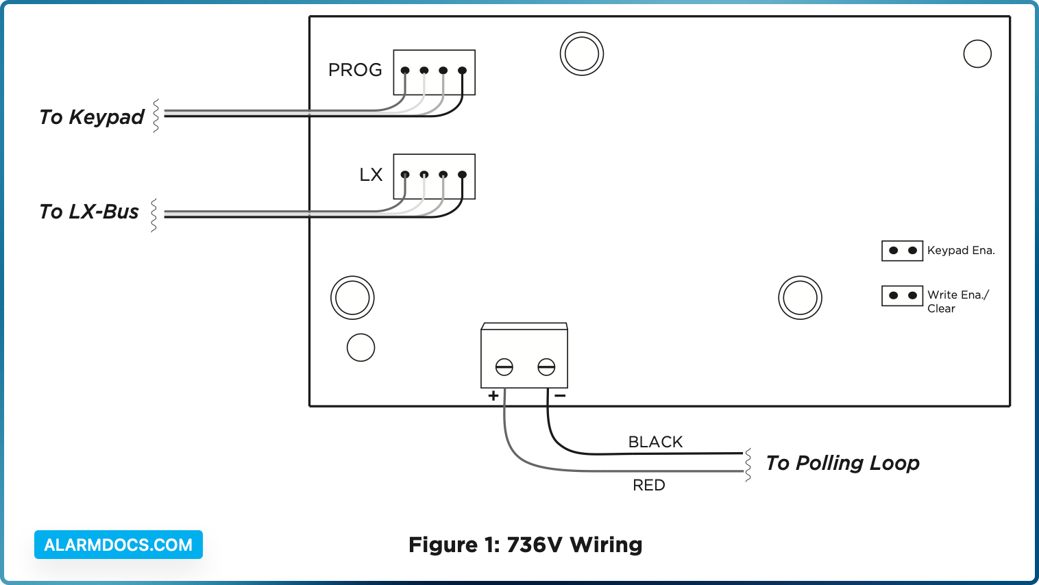
Refer to Figure 1 for jumper locations and wiring connections.
- 1. Power down the panel and connected devices.
- 2. Place the jumper across both 736V programming pins (Write Ena/Clear) to put the module into autolearn mode.
- 3. Power up the control panel. Allow the panel and connected devices to stabilize for a few minutes.
- 4. Devices begin to auto-enroll their serial numbers into the 736V. Some devices may trip to report their serial number.
- 5. Remove the jumper from both programming pins (Write Ena/Clear).
- 6. Place the jumper on both keypad diagnostics output pins (Keypad Ena), then connect a DMP keypad to the 736V PROG header. Press the first key in the top row select area to enter the 736V menu (PNT).
Locate Devices
If you don’t have access to the V‑Plex device serial numbers and names, you can use the Zone Finder function to determine which zone corresponds to a specific device.
- 1. Reset the panel. Enter 2313 (DIAG), then press CMD.
- 2. Press CMD to display ZONE FINDER. Press any select key or area. The display changes to FAULT ZONE.
- 3. Short the zone. The next zone on the system that changes from a normal to an open or shorted state is displayed as ZONE NO: * * *. Record the zone number and its name. To continue, press the back arrow key and short the next zone.
- 4. After collecting the zone numbers and names, return to the panel to change the names of the programmed zones.
Program V‑Plex Zones
After completing each of the following steps, press CMD to advance to the next option.
- 1. Reset the panel. Enter 6653 (PROG) at the panel keypad and go to ZONE INFORMATION.
- 2. At ZONE NO, enter the device zone that corresponds to the LX‑Bus.
- 3. At *UNUSED*, enter the zone name.
- 4. At ZONE TYPE, select the zone type.
- 5. At the Area Assignment section, select the area.
- 6. At the NEXT ZN? prompt, select YES.
- 7. Repeat steps 2 through 10 for the remaining devices.
- 8. To save panel programming, go to STOP and press CMD
Test Zones
Perform a Burglary Zone Walk Test to confirm that all of the devices are properly configured and communicating with the panel.
- 1. Reset the panel.
- 2. At a keypad, enter 8144 (WALK) and select BG.
- 3. Trip each zone on the system for 1 to 2 seconds. The keypad will annunciate each time a zone is tripped and display the number of zones successfully tripped.
- 4. Press the fourth select area or key to end the Walk Test.
Point Status Display
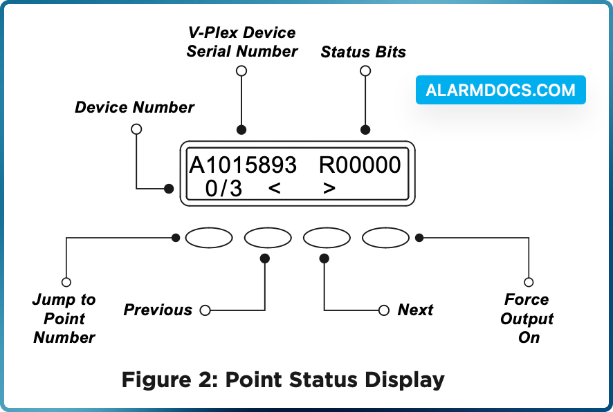
A keypad connected to the 736V displays the status and serial numbers of enrolled V‑Plex devices. Refer to the following descriptions and Figure 2 to learn how to read the point status display.
V‑Plex Zone Address
In the address, A indicates that the device is an Honeywell product. In Figure 2, A1015893 is a device with serial number 1015893.
Status Bits (Relay)
In the status bits, the first number represents the relay state. R indicates that the relay is off. 0 (zero) indicates that the relay is on. F indicates that FORCE OFF is enabled and the output state is forced on. In Figure 2, the relay is off as indicated by R in the first bit of the status code.
Status Bits (General Device States)
The next five bits in the status code represent general device bit states. T indicates zone short, A indicates zone open, and 0 (zero) indicates normal. The status code in Figure 2 indicates that the device is working normally.
Device Number
The first digit of the device number is the current device zone in the 736V. The second number is the total number of devices in the database map. Because device numbers start at 0 (zero), the last device zone will be the second number minus one. For example, the last device in a set of three will display as 2/3. In Figure 2, the current device is the first device out of three, displayed as device 0/3.
Point Status
This allows you to view the status of each output point (zone) on the polling loop.
ADDITIONAL INFORMATION
Turn on Outputs
Smoke and PIR motion detector zones require that the output corresponding to the programmed zone are turned on to report the status correctly. For example, if you have a PIR on zone 503, output 503 will need to be toggled on for the zone to report correctly.
Go to the User Menu, enter a valid code that has output authority. Go to OUTPUTS ON/OFF? and enter the output number that corresponds to the zone. Select top row key 3 to toggle the output ON.
Reboot the 736V
Before rebooting the module, remove the jumper from the Write Ena/Clear header. To reboot, turn the last LX‑Bus output off, then back on. For example, if the module is connected to LX500, turn output 599 off, then back on.
Reuse a 736V V‑Plex Module
Before reusing a 736V, delete all data in the module by placing the jumper across both programming pins (Write Ena/Clear) and powering up the panel.
Module Supervision Zones
The module supervision zones for the 736V include zones 96‑99 on each LX‑Bus header, such as 596‑599 on LX500. These module supervision zones display open, short, or normal depending on zone condition.
Zones 597, 697, 797, 897, and 997
- OPEN —The module is not connected or has lost communication with the panel
- SHORT—A jumper is on both programming pins (Write Ena/Clear) and the module is in autolearn mode
- NRML (Normal)—A jumper is not on both programming pins (Write Ena/Clear) and the module is not in autolearn mode
Zones 598, 698, 798, 898, and 998
- OPEN—The module is not connected or has lost communication with the panel
- SHORT—A jumper is on both keypad diagnostic output pins (Keypad Ena) and the module is in keypad diagnostic mode
- NRML (Normal)—A jumper is not on both keypad diagnostic output pins (Keypad Ena) and the module is not in keypad diagnostic mode. When not using keypad diagnostics, keep this jumper removed to avoid slowing polling device operation on the system
Zones 599, 699, 799, 899, and 999
- OPEN—The module is not connected or has lost communication with the panel
- SHORT—The polling circuit is shorted, a V‑Plex device is wired with incorrect polarity, or the polling circuit is wired to the module incorrectly
- NRML (Normal)—The module is connected and is communicating with the panel correctly