Alarm Docs
  • Submit Article
  • Contact Us
  • About Us
  1. Home
  2. Qolsys
  3. Qolsys IQ4: Sensor status icons
Searching...

Other Articles

  • Program CID format on a PC4020
  • Program a module on a Fire-Lite ES-200X
  • Program DSC PC5010 to use Contact ID
  • IQ5: Firmware Updates
  • IQ INSTALLER
  • DMP: 860 relay module
  • 711: Zone Expansion Module
  • GEMC-EZM8 – Installation Instructions
  • PG-WLSHW: Wiring a fire zone
  • EVD-2 wiring with 2 additional EVD-R
  • Vista: How to enable Contact ID
  • DMP: How to program static IP
  • ADC: Internet connection type compatibility
  • StarLink SLE-LTE: Wiring diagram
  • StarLink SLE-LTE: Terminal Descriptions
  • PowerSeries Neo: Change entry delay
  • Vista: How to program house code
  • How to address 6160 keypad on Vista 21
  • 1100DH: Installation Guide
  • OPTEX Beams: Master/slave selector switch setting
  • Lynx: Summary of connections
  • PROTAKEOVER: Setup guide
  • PGP922: Installation Guide
  • Qolsys IQ4: How to disable the panel camera
  • Qolsys IQ4: How to disable the panel tamper

Qolsys IQ4: Sensor status icons

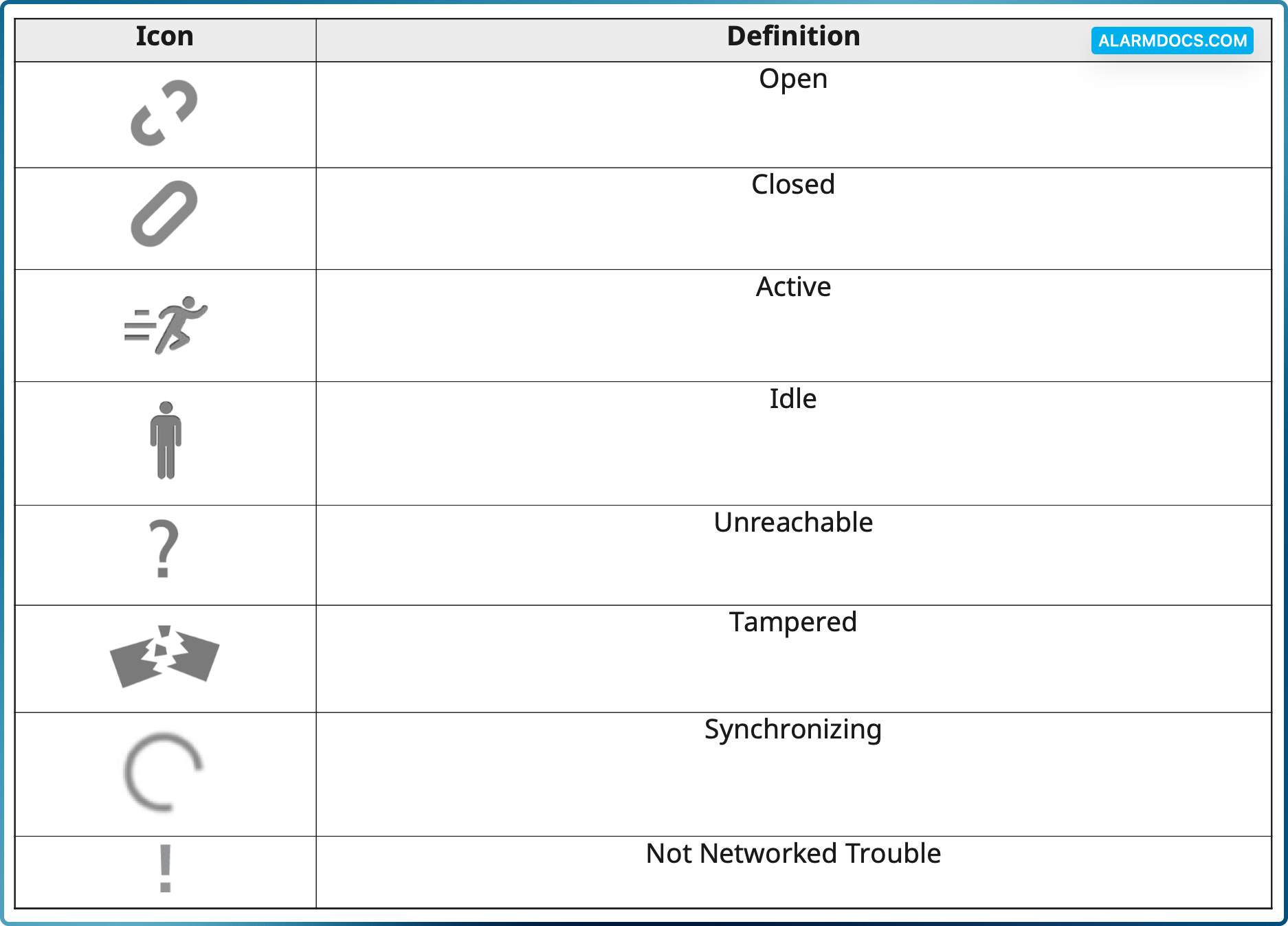
The image below illustrates the definition of status icons on the IQ2 and IQ4 panels. This definition also applies to remote keypads connected to the IQPro panel.

Tagged: iconsstatus
Was this article helpful?
Yes No
© Copyright 2026 - AlarmDocs.Com