Alarm Docs
  • Submit Article
  • Contact Us
  • About Us
  1. Home
  2. Fire Alarm
  3. NFS-640: Circuit Board Components
Searching...

Other Articles

  • DMP XF6: Accessory devices
  • Reset Alula radio/communicator
  • How to add a zone to a VISTA H3
  • DMP XF6: Programming requirements
  • DMP XF6: Compatibility
  • DMP XF6: Wire the panel
  • DMP XF6: Install the panel
  • DMP XF6: Specifications Summary
  • XF6: Operating Instructions
  • Radionics: D168 Module Installation
  • PROA7PLUS: Re-register the radio
  • Install piezo on Honeywell Vista 21
  • S2000 – How to enter programming
  • DMP: Version 263 Update
  • Qolsys IQ4: Latest firmware version
  • Napco GEM-P1632: Error codes
  • Honeywell VISTA-128BPT compatible devices
  • Honeywell Vista 128BPT: ECP Error
  • Updating firmware on an Alula cellular communicator
  • How to update NAPCO StarLink firmware
  • How to adjust thermostat from IQ Panel 5
  • Create a guest code on the Qolsys IQ5
  • Programming VISTA-21iP for internet-only
  • Program user code on DMP XR/XT panel
  • Program the on-board triggers on Vista 21

NFS-640: Circuit Board Components

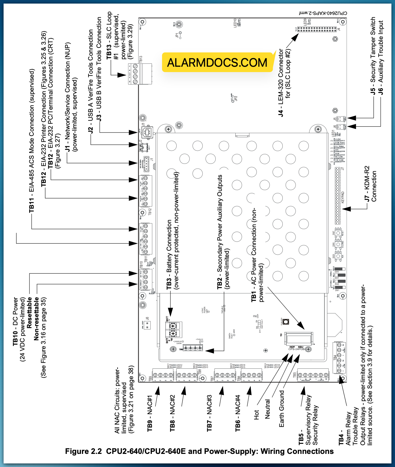
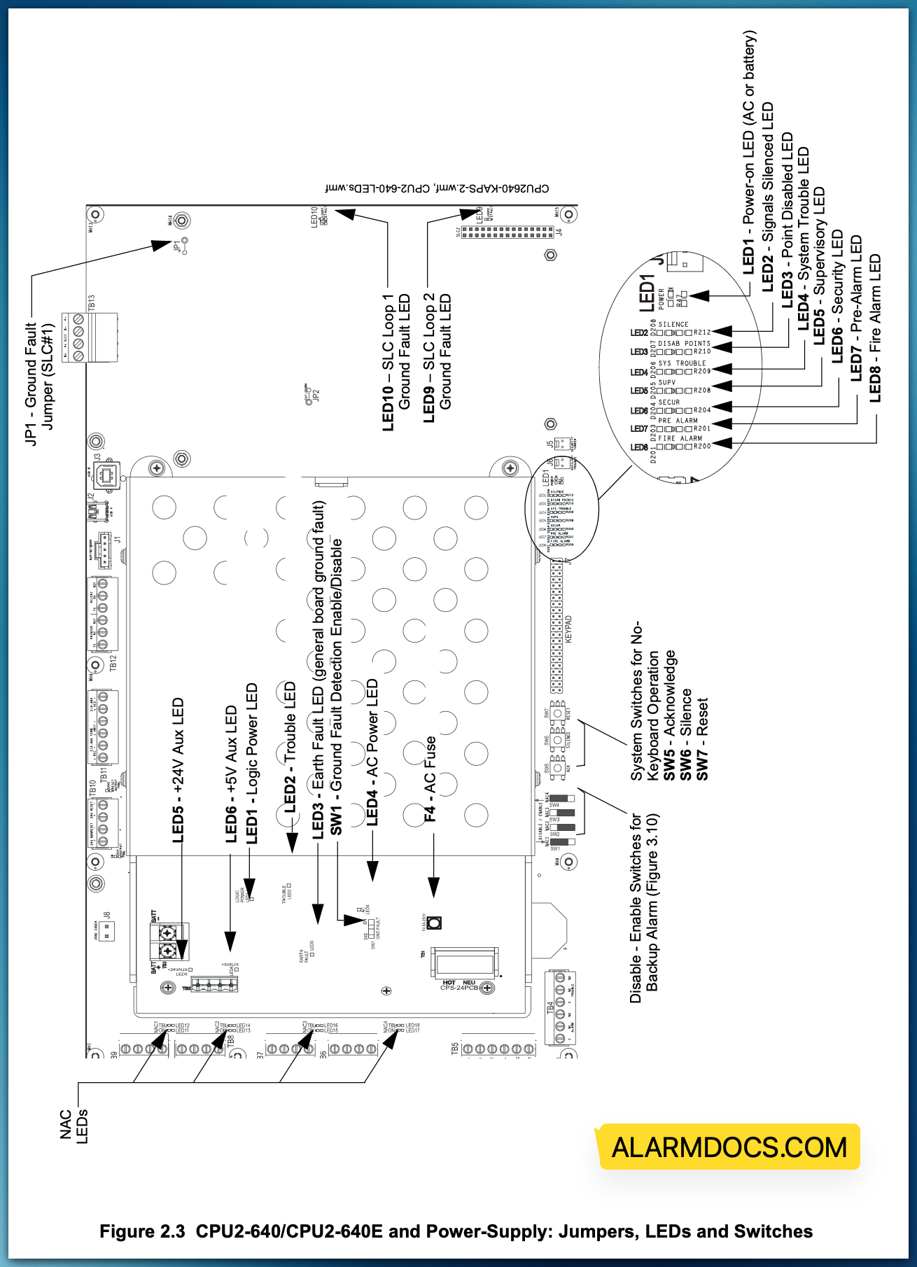
The following two figures illustrate the location of the various connections, switches, jumpers and LEDs on the CPU2-640/CPU2-640E and its power supply. Figure 2.2 shows wiring connections; Figure 2.3 shows jumpers, LEDs and switches. See Section 3 “Installation” for larger images and more details. (Larger images are referenced on these drawings.)
Tagged: nfs640
Was this article helpful?
Yes No
© Copyright 2026 - AlarmDocs.Com